


- Comparative Performances of Electrically Conductive Adhesives by Incorporation of Silver, Silver-Coated Copper, and Graphene
Kyung-Soo Sung and Namil Kim*,†

Research & Development Center, Protavic Korea, Daejeon 34326, Korea
*Environmental Materials R&D Center, Korea Automotive Technology Institute, Chungnam 31214, Korea- 은, 은 코팅된 구리, 그래핀 첨가에 따른 도전성 접착제의 성능 비교
성경수 · 김남일*,†
(주)프로타빅코리아 연구개발부, *자동차부품연구원 친환경소재연구센터
The effect of conductive fillers on electrical and adhesion properties of electrically conductive adhesives (ECAs) has been investigated. The ECAs were prepared by incorporating different conductive fillers such as silver (Ag), silver-coated copper (AgCu), and graphene into epoxy binder. At constant filler concentration, the Ag-filled ECAs exhibited the lowest bulk resistivity at around 3.6×10⁻⁴ Ω·cm as compared to the ECAs filled with Ag/AgCu and Ag/AgCu/graphene. Adhesion strength between silicon die and metallic lead frame showed systematic drop upon addition of graphene. Under 85 ℃ and 85% humidity environment, the bulk resistivity of the Ag/AgCu and Ag/AgCu/graphene-filled ECAs decreased with aging time due to the increase of crosslink density while the Ag-filled ECAs remained stable. Adhesion strength decreased with aging time.
전도성 필러의 종류에 따른 도전성 접착제의 전기적, 접착특성 변화에 대해 살펴보았다. 은, 은 코팅된 구리, 그래핀을 전도성 필러로 사용하였고 에폭시 기재와 혼합하여 제조되었다. 필러 함량을 고정한 상태에서 전기적 특성을 확인해 본 결과 순수한 은을 함유한 접착제에서 3.6×10⁻⁴ Ω·cm의 저항을 보여 다른 필러에 비해 우수한 전도성을 보였고 실리콘 기판과 금속 리드프레임간 접착력은 그래핀의 함량에 비례하여 저하되는 것으로 나타났다. 85 ℃, 85% 상대습도 환경에서 특성 변화를 살펴보면 은을 함유한 접착제는 노출 시간에 관계없이 낮은 저항값을 유지한 반면 은/은 코팅된 구리, 은/은 코팅된 구리/그래핀이 첨가된 접착제는 추가적인 경화로 인해 오히려 낮아졌다. 접착력은 필러의 종류에 상관없이 노출 시간에 따라 감소하였다.
The effect of conductive fillers on electrical and adhesion properties of electrically conductive adhesives (ECAs) has been investigated. The Ag-filled ECAs exhibited high electrical conductivity and adhesion strength, but the use of commercial graphene as conductive filler is premature by conventional preparation technique.
Keywords: electrically conductive adhesives, graphene, silver, silver-coated copper, electrical conductivity, adhesion strength, aging test
This work was supported by Development of Industrial Materials and Technologies Project of Ministry of Trade, Industry and Energy (grant number 20000391).
Electrically conductive adhesives (ECAs) have been widely adopted as tin-lead solder replacement in microelectronic assemblies because of environmental safety, low space occupancy, and low thermal stress on the substrates.1-3 In industry, most ECAs consist of thermally curable epoxy binders and micro-sized silver (Ag) flakes. The epoxy/Ag composites exhibit excellent electrical conductivity and chemical durability with benign adhesion strength to metallic lead frames.4-6 Other metallic fillers such as nickel (Ni), aluminum (Al), and copper (Cu) reveal comparable electrical conductivity but they are vulnerable to oxidation upon prolonged exposure to outdoor environment. High electrical conductivity can be achieved by increasing the Ag content, but high filler loading generally lowers the impact strength and processibility. Moreover, high cost of the Ag powders limits its wide usage. Several efforts have been made to obtain the ECAs with low production cost and high reliability. Silver-coated copper (AgCu) can reduce the manufacturing cost, where the protective Ag layer prevents the oxidation reaction of Cu.7-10 However, the AgCu-filled ECAs are generally reliable when the interface between Cu and Ag is not in contact with moisture and oxygen especially at elevated temperature.
When micro-sized fillers are used, higher filler loading is unavoidable in order to meet required electrical conductivity. Recently, the ECAs filled with nano-sized carbon such as carbon nanotube (CNT) and graphene have received immense interest because of superior electrical conductivity and low density.11-14 The performance of nanocomposites is mainly affected by the aspect ratio of conductive fillers and degree of distribution in a matrix. Electrical conductivity of the nano-carbon loaded ECAs is often unsatisfactory for commercial uses because of poor dispersion and processibility. Various approaches such as surface modification and physical mixing have been suggested to facilitate dispersion of the nanofillers. Combination of nano-sized fillers with the micro-sized fillers is another approach to improve the loading efficiency where the nano-sized fillers not only fill the gaps or voids between micro-sized fillers but also construct the additional conductive pathways.15-18 In hybrid system, the selection of appropriate fillers is of particular importance to generate the synergistic effect. In present work, we investigated the effect of conductive fillers on the electrical conductivity and adhesion property of the ECAs. Commercial graphene was directly incorporated into the Ag and AgCu-filled ECAs by a conventional mill method. The performances of various ECAs were further examined after aging under thermal (85 ℃) and humidity (85%) environment.
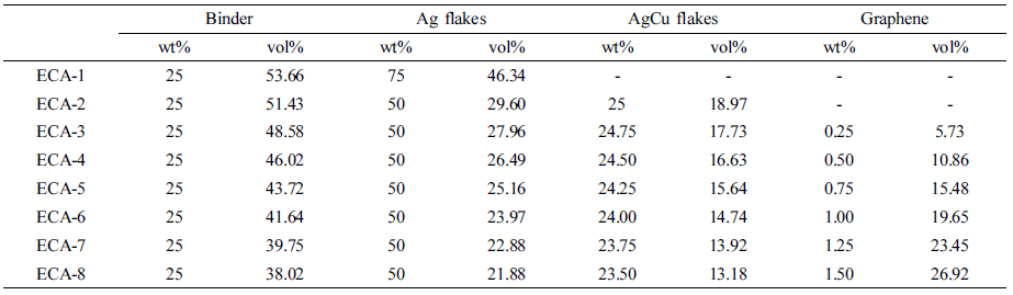
Materials and Sample Preparation. The epoxy binder is composed of 62.5 wt% phenol novolac epoxy (EEW: 165~185 g/eq), Kukdo Chemicals), 27 wt% epoxy diluent (1,4-butanediol diglycidylether, Kukdo Chemicals), 10 wt% curing agent (1-cyanoethyl-2-ethyl-4-methylimidazole, Shinkoku Chemicals), and 0.5 wt% silane coupling agent (3-glycidoxypropyltrimethoxy silane, Sigma-Aldrich). A predetermined ratio of conductive fillers including silver flakes (5 μm, EA-0295, Metalor), silver-coated copper flakes (3 μm, CFM03S25T, Join M), and graphene powders (5 μm, xGnP-M-5, XG Sciences) was uniformly dispersed into the binder using a three roll mill and then rotated at 200 rpm for 30 min in a vacuum bath to remove the residual bubbles. Thermal curing was performed at 175 ℃ for 30 min. The ratio of epoxy binder and conductive fillers in ECAs remains at 25 wt% and 75 wt%, where the relative Ag/AgCu/graphene content are varied. The composition of the ECAs is listed in Table 1.
Characterization. Thermal stability of ECAs was investigated using thermogravimetric analysis (TGA). Approximately 10 mg of samples was heated from 30 to 500 ℃ at a rate of 10 ℃/min under air environment. The bulk resistivity (ρ) was calculated from the resistance (R) of a rectangular specimen having dimension of 30 mm in length (L) × 3 mm in width (w) × 0.05 mm in thickness (t), i.e., ρ = (R×w×t)/L. The resistance was measured using a multi-meter (7600RLC, QuadTech). Die shear test (Dage series 4000) was conducted to measure the adhesion strength. The shear force required to detach the square silicon die (1.25 mm × 1.25 mm, 350 μm of thickness) from the lead frame was measured. The results were averaged from the five sets of tested samples.
The effect of heat and moisture exposure on the electrical conductivity and adhesion property has been examined. The adhesive film was placed in a temperature and humidity chamber (Jeiotech) maintained at 85 ℃ and 85% relative humidity (RH). The weight gain by water absorption has been measured as a function of exposure time. The viscoelastic behavior was probed in a sinusoidal tension mode using Pyris Diamond DMA (Perkin Elmer) technique. The cured film (200 mm in length × 6 mm in width × 0.3 mm in thickness) was heated from 25 to 280 ℃ at a heating rate of 2 ℃/min under nitrogen environment. The frequency of the dynamic mechanical measurement was fixed at 1 Hz.
|
Table 1 Designation and Composition of the ECAs Containing Different Conductive Fillers |
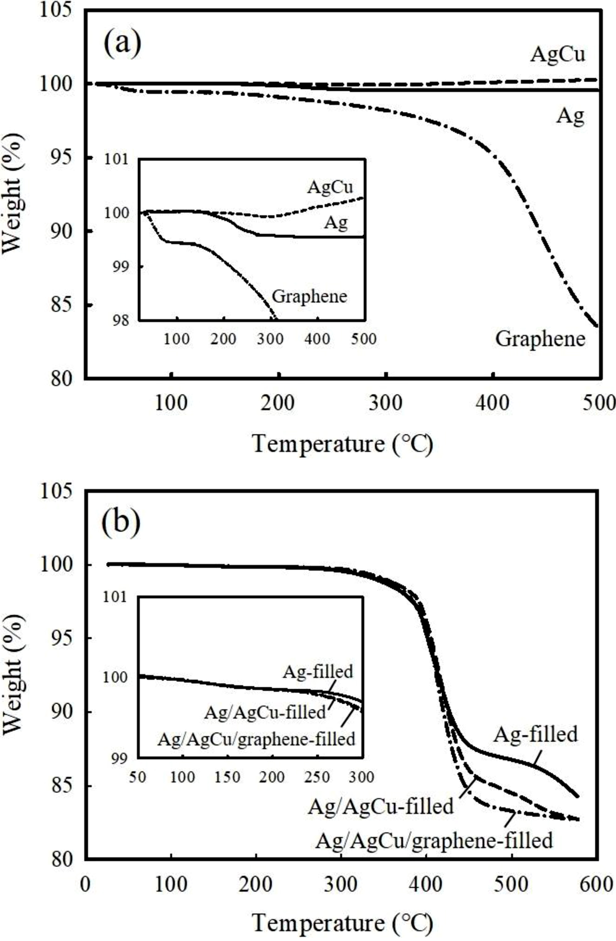
Electrical and Adhesion Properties of ECAs. Figure 1(a) depicts the TGA thermograms of the pure conductive fillers. The Ag flakes prove to be thermally stable up to 500 ℃, exhibiting a slight weight loss below 0.5% in the temperature range from 200 to 250 ℃. It may be attributed to the removal of an organic lubricant present on the surface. The AgCu flakes also show the similar behavior below 250 ℃, but they undergo thermal oxidation with weight gain over 0.3% at 500 ℃. The TGA curve of graphene reveals a gradual weight loss from 50 ℃ and reaches around 83% residue at 500 ℃. The oxygen-containing moieties on the surface may be evaporated during a course of heating. Figure 1(b) displays the thermal stability behavior of the as-cured adhesives. Major reduction between 300 and 400 ℃ may correspond to the decomposition of the organic epoxy matrix. No weight loss occurs below 250 ℃, but the ECAs filled with AgCu and graphene start to decompose when heated above 250 ℃, albeit slight, due to the evaporation of the unreacted epoxy binder. It is hypothesized that the curing reaction between epoxy and hardner is hampered in the presence of oxygen-containing groups on the graphene and AgCu surfaces.
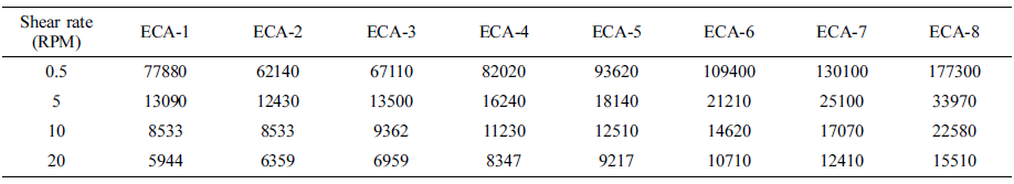
Viscosity is one of the crucial criteria to determine the printing method of adhesives for electronics applications. In general, the viscosity in the range of 8000 to 30000 cPs is recommended for dispensing purposes. As summarized in Table 2, the ECAs containing Ag and Ag/AgCu exhibit relatively low viscosity regardless of shear rate despite the same filler loading. At 5 rpm, for example, the ECAs show 13090 and 12430 cPs, respectively. Good wettability of the metallic flakes within the binder is responsible for low viscosity. Upon addition of graphene, however, the viscosity increases dramatically due to high volume fraction in combination with partial agglomerates of the graphene. Since the proper viscosity for pin transfer screen dispensing and printing processes is recognized as to be below 30000 cPs, the adhesive containing below 1.5 wt% graphene is favorable for commercial uses.
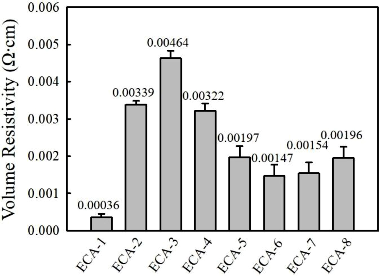
Figure 2 shows the electrical conductivity of various ECAs at 75 wt% conductive filler loading. The Ag-filled ECAs exhibit the lowest bulk resistivity of 3.6×10⁻⁴ Ω·cm, while the ECAs filled with the combined 50 wt% Ag and 25 wt% AgCu reveal one order of higher resistivity, i.e., 3.4×10⁻³ Ω·cm. When 0.25 wt% of graphene is added to the Ag/AgCu-filled ECAs, the bulk resistivity further increases up to 4.6×10⁻³ Ω·cm. It is expected that the addition of a small amount of graphene destroys the conductive channels constructed by micron-sized Ag and AgCu. Upon increasing graphene content above 0.5 wt%, the resistivity starts to decrease and reach around 1.5×10⁻³ Ω·cm at 1 wt%. The increased contact area between the conductive fillers may contribute to form new electrically conductive channels.12,19 Above 1.5 wt%, the resistivity increases again due to the occurrence of agglomeration. The enhanced viscosity of adhesives by addition of graphene is unprofitable to achieve the high degree of dispersion. Graphene itself has a strong tendency to agglomerate which affect the performance of the graphene-epoxy composites such as electrical conductivity and mechanical properties. On the other hand, the commercial Ag and Ag-coated Cu flakes are coated with a fatty acid lubricant. This organic layer improves the dispersion of the Ag and Ag-coated flakes with reduced viscosity of the adhesives. Therefore, the optimum graphene content in adhesives is selected as 0.75 and 1 wt%.
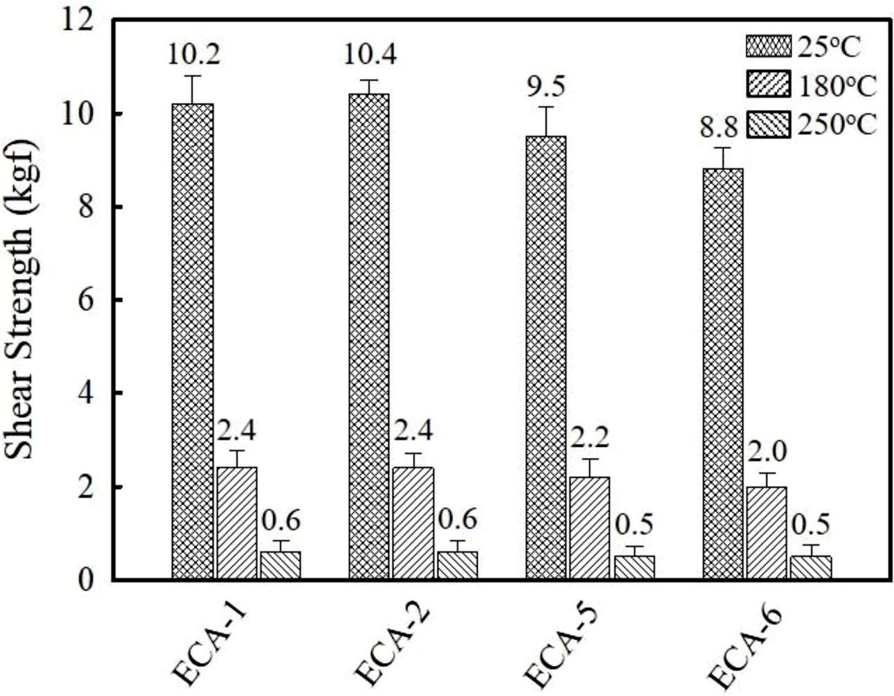
The effect of conductive fillers on adhesion strength has been examined by monitoring die shear strength between silicon die and Ag lead frames. As shown in Figure 3, the Ag- and Ag/AgCu-filled ECAs show the similar bond strength at ambient temperature, i.e., 10.2 and 10.4 kgf. Since silicon die is used as counterpart, the compatibility between adhesive and substrate may affect the adhesion strength. When graphene is added, shear strength on Ag lead frame decreases, revealing 9.5 kgf at 0.75 wt% and 8.8 kgf at 1 wt%. Additional solid-to-solid contact points may weaken the adhesion strength. The adhesives used in electronic circuits are generally exposed to high temperature environment during the assembly and handling processes such as wire bonding and reflow. Therefore, the preservation of adhesion strength at high temperature is important to ensure the reliability. Die shear test was conducted at 180 and 250 ℃ which corresponds to a wire bonding and reflow temperature. As described in Figure 3, die shear strength decreases dramatically at elevated temperature. At 180 ℃, the Ag and Ag/AgCu-filled ECAs show the adhesion strength value of 2.4 kgf, which is about 7.5 kgf lower than the measured value at 25 ℃. The adhesive containing 0.75 and 1 wt% graphene reveal the adhesion strength of 2.2 and 2.0 kgf, respectively. Upon further increasing temperature up to 250 ℃, the die shear strength is reduced below 0.6 kgf regardless of the conductive fillers. The low adhesion strength results from the differences in thermal expansion and mechanical properties between adhesives and substrates.
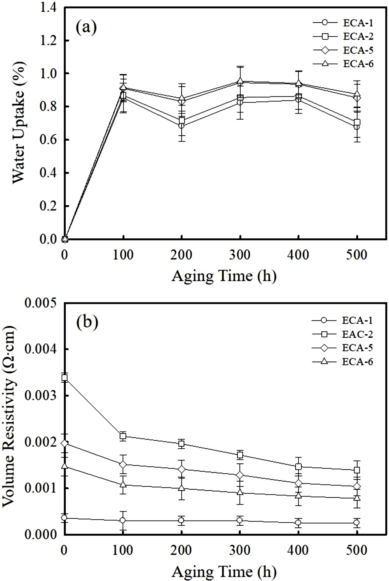
Electrical and Adhesion Properties of ECAs after Aging. The moisture uptake of the as-cured ECAs has been monitored during humid and thermal cycle under 85 ℃ and 85% RH environment. As shown in Figure 4(a), the moisture uptake increases noticeably for the first 100 h and then remains stable in the range of 0.6-1.0%. Hydrophilic nature of epoxy binder along with the voids present at the interfaces is responsible for the moisture absorption. The adhesives containing 0.75 and 1 wt% graphene reveal a slightly higher absorption above 0.9 % due to the hydrophilic oxide groups on the surface. Figure 4(b) exhibits the variation of bulk resistivity as a function of aging time. The Ag-filled ECA shows no significant change revealing 2.5×10⁻⁴ Ω·cm after 500 h. It indicates that the thermal and humid environment rarely affects the electrical property. On the other hand, the bulk resistivity of Ag/AgCu-filled ECA decreases below 2.1×10⁻³ Ω·cm for the first 100 h and then gets stable at around 1.4×10⁻³ Ω·cm after 400 h. The increment in conductivity is also observed for the Ag/AgCu/graphene-filled ECAs although the level of decrement is less significant. In the initial stage of aging cycles, the epoxy binders may undergo a post-polymerization with volumetric shrinkage and therefore the contact areas between the conductive fillers increases.20,21 The bulk resistivity of ECAs containing 1 wt% graphene is reduced from 1.5×10⁻³ to 7.8×10⁻⁴ Ω·cm after aged for 500 h. In spite of increment in conductivity, the appearance of Ag/AgCu-filled ECAs turns into a brownish color due to oxidation reaction of the AgCu during thermal and humid aging.
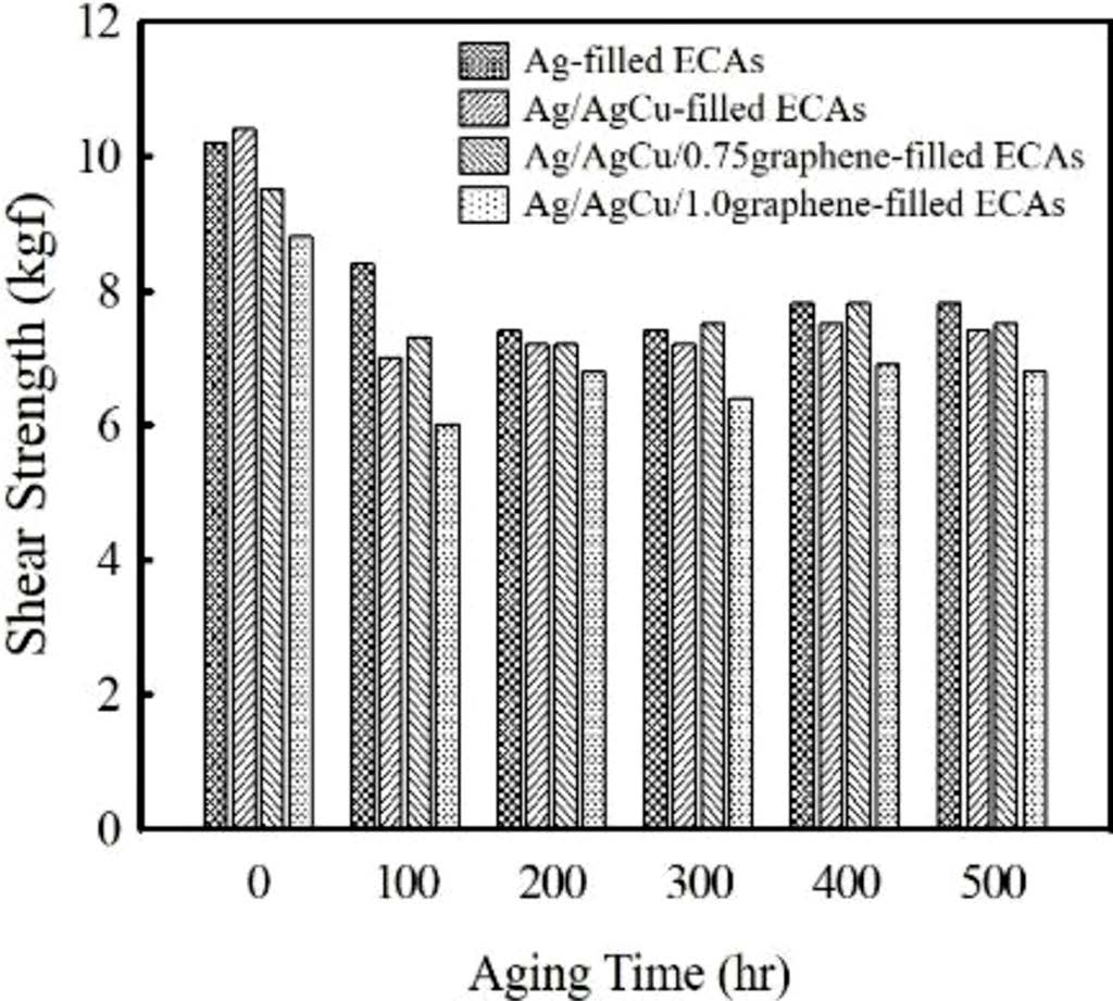
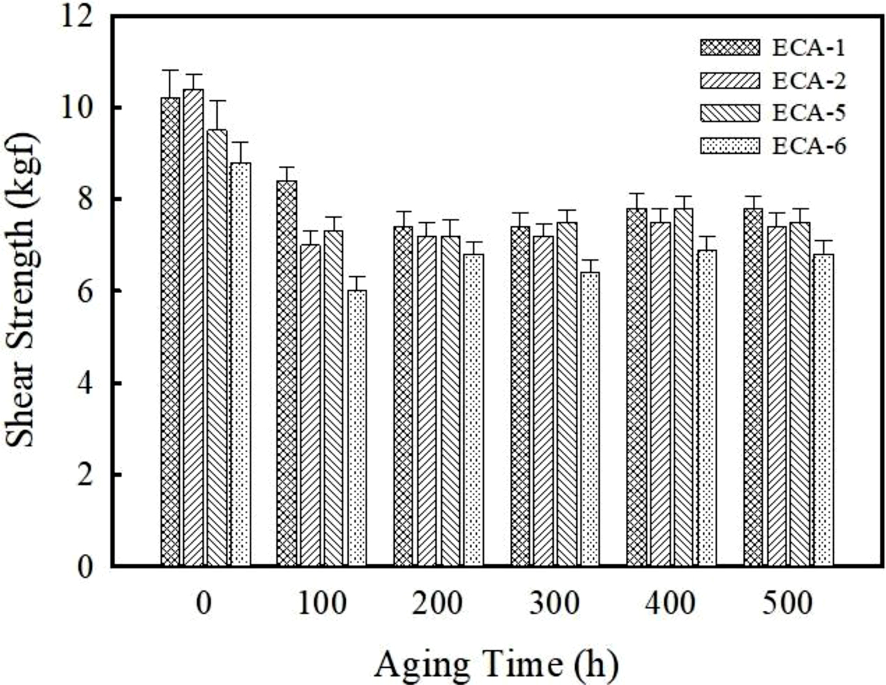
Figure 5 shows the variation of die shear strength on Ag lead frame with aging time. After 500 h, the die shear strength of the Ag and Ag/AgCu-filled ECAs decreases from 11.2 to 7.8 MPa (approximately 30% reduction) and 11.8 to 7.4 MPa (37% reduction), respectively. The reduced adhesion strength under the moisture and thermal environment is associated with the plasticization effect of absorbed moisture and mismatch of coefficient of thermal expansion (CTE) between the adhesive and metallic substrate. Upon addition of graphene, the magnitude of decrement slows down. Upon addition of 1 wt% graphene, the die shear strength decreases about 9.3%, i.e. from 7.5 to 6.8 MPa. As reported in carbon nanotube (CNT)-filled ECAs system, the graphene may reduce the CTE value of adhesives and consequently the stress generated by thermal and humid expansion is suppressed.22,23
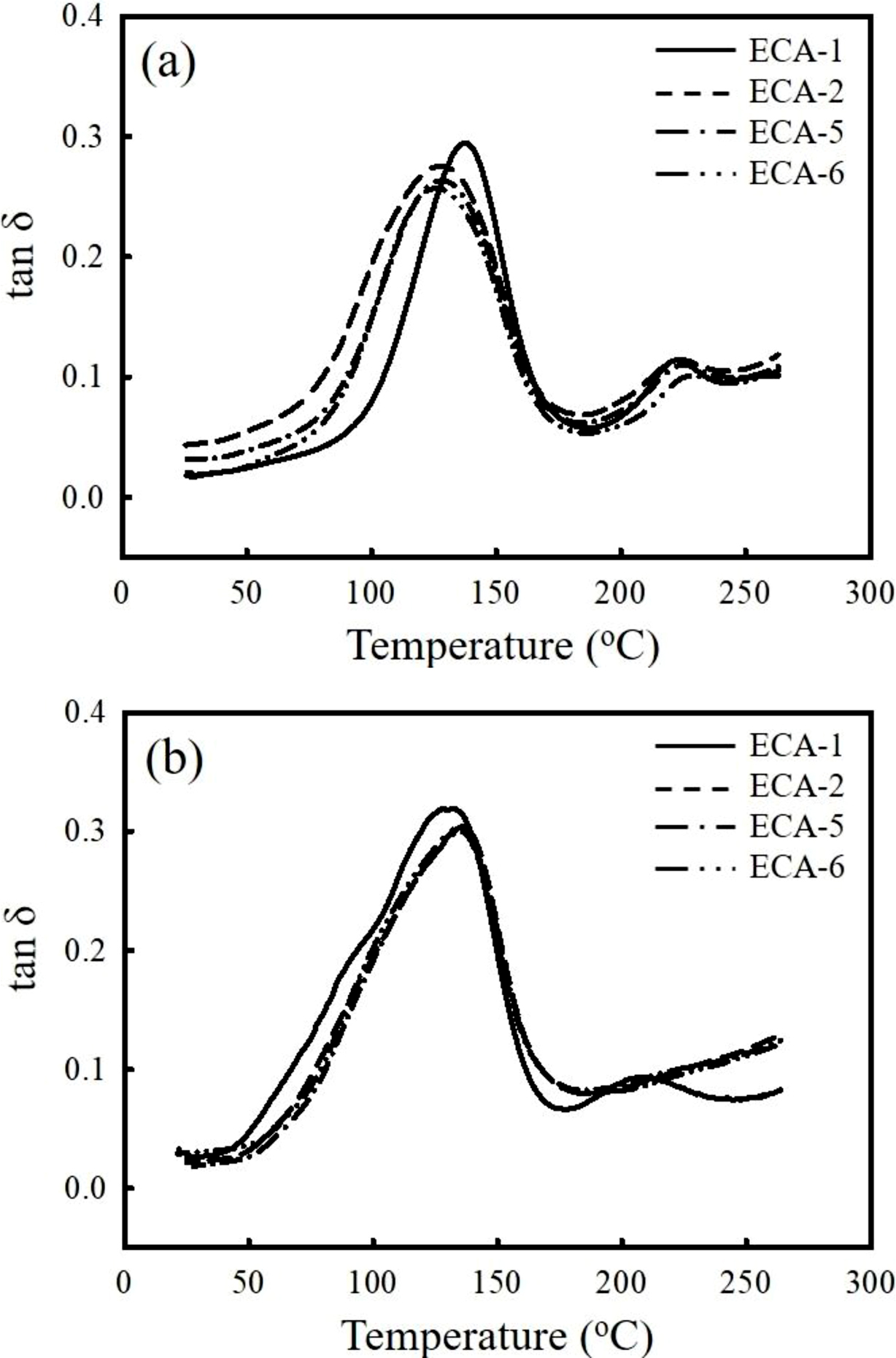
Figure 6(a) shows the plots of loss tangent (tan δ) curve versus temperature for the ECAs. In the Ag-filled ECA (ECA-1), major peak is observed at 138 ℃ which is about 10 ℃ higher than other adhesives and moreover the peak is more pronounced. Glass transition temperature (Tg) corresponding to the tan δ peak is generally observed at high temperature when the crosslinking density is high. Another minor peak appears at around 220 ℃ may be a consequence of the segmental motion of the binder molecules in the rubbery region. After thermal and humid cycling, the tan δ peak of the ECA-1 slightly shifts to a lower temperature around 132 ℃ due to the diluent effect of absorbed moisture. Meanwhile, the Tg of the ECAs containing AgCu and graphene increases more than 5 ℃ after aged for 500 h, exhibiting a similar peak position near 136 ℃. It is estimated that additional cross-linking reaction takes place during long-term exposure to high temperature. Since the effect of moisture absorption and additional crosslinking reaction on the Tg is opposite, the additional crosslinking reaction tends to dominate the dynamic mechanical behavior over the moisture effect.
|
Figure 1 TGA thermograms of (a) pure silver (Ag); silver-coated copper (AgCu), graphene; (b) as-cured ECAs containing Ag, Ag/AgCu, Ag/AgCu/graphene fillers. The thermograms were obtained at a heating rate of 10 ℃/min under air atmosphere. |
|
Figure 2 Comparison of bulk resistivity for Ag-, Ag/AgCu-, Ag/AgCu/graphene-filled ECAs. |
|
Figure 3 Comparison of die shear strength between silicon die and metallic frame performed at 25, 180, and 250 ℃. |
|
Figure 4 Plots of (a) moisture uptake; (b) bulk resistivity as a function of aging time of the ECA-1, ECA-2, ECA-5, ECA-6. The aging test was performed at 85 ℃ and 85% RH for 500 h. |
|
Figure 5 Plot of adhesion strength as a function of aging time for Ag-, Ag/AgCu-, Ag/AgCu/graphene-filled ECAs. The aging test was performed at 85℃ and 85% RH for 500 h. |
|
Figure 6 Comparison of the tan δ curves of the ECAs obtained (a) before; (b) after aging test. DMA scan was conducted at a heating rate of 2 ℃/min. |
|
Table 2 Viscosity of the ECAs Filled with Ag, AgCu, Graphene Fillers Obtained at Different Shear Rates |
The performances of the ECAs has been tested and compared by varying the conductive fillers. At the equal filler loading, the Ag-filled ECAs exhibited good electrical conductivity and adhesion strength in comparison to the Ag/AgCu- and Ag/AgCu/graphene-filled ECAs. The addition of a small amount of graphene less than 1.25 wt% was effective to increase the electrical conductivity of Ag/AgCu-filled ECAs with benign viscosity. Under 85 ℃ and 85%RH humidity environment, the additional crosslinking reaction occurred for the ECAs containing AgCu and graphene while the Ag-filled ECA showed stable behavior. From the electrical conductivity and adhesion strength, it can be concluded that the use of commercial graphene as conductive filler is premature by conventional preparation technique. Introduction of proper functional groups on graphene surface along with the selection of appropriate mixing system is needed to improve the properties.
- 1. V. R. Manikam and K. Y. Cheong, IEEE Trans. Compon. Packag. Manuf. Tech., 1, 457 (2011).
-

- 2. Y. Li and C. P. Wong, Mater. Sci. Eng. R, 51, 1 (2006).
-
- 3. I. Mir and D. Kumar, Int. J. Adhes. Adhes., 28, 362 (2008).
-
- 4. H.-W. Cui, Q. Fan, and D.-S. Li, Int. J. Adhes. Adhes., 48, 177 (2014).
-
- 5. Y. Guan, X. Chen, F. Li, and H. Gao, Int. J. Adhes. Adhes., 30, 80 (2010).
-
- 6. H. Jiang, K. S. Moon, Y. Li, and C. P. Wong, Chem. Mater., 18, 2969 (2006).
-
- 7. H.-M. Ren, K. Zhang, Y. M. Matthew, X.-Z. Fu, R. Sung, and C. P. Wong, J. Solid State Light, 1, 1 (2014).
-
- 8. R. Zhang, W. Lin, K. Lawrence, and C. P. Wong, Int. J. Adhes. Adhes., 30, 403 (2010).
-
- 9. H. Nishikawa, S. Mikami, K. Miyake, A. Aoki, and T. Takemoto, Mater. Trans., 51, 1785 (2010).
-
- 10. C. K. Kim, G. J. Lee, M. K. Lee, and C. K. Rhee, Powder Technol., 263, 1 (2014).
-
- 11. A. Santamaria, M. E. Munoz, M. Fernandez, and M. Landa, J. Appl. Polym. Sci., 129, 1643 (2013).
-
- 12. H.-W. Cui, A. Kowalczyk, D.-S. Li, and Q. Fan, Int. J. Adhes. Adhes., 44, 220 (2013).
-
- 13. H. Ma, M. Ma, J. Zeng, X. Guo, and Y. Ma, Mater. Lett., 178, 181 (2016).
-
- 14. B. M. Amoli, J. Trinidad, G. Rivers, S. Sy, P. Russo, A. Yu, N. Y. Zhou, and B. Zhao, Carbon, 91, 188 (2015).
-
- 15. W. Yuan, Q. Xiao, L. Li, and T. Xu, Appl. Therm. Eng., 103, 1067 (2016).
-
- 16. R. Ma, S. Y. Kwon, Q. Zheng, H. Y. Kwon, J. I. Kim, H. R. Choi, and S. H. Baik, Adv. Mater., 24, 3344 (2012).
-
- 17. Y. Zhang, S. Qi, X. Wu, and G. Duan, Synth. Met., 161, 516 (2011).
-
- 18. H. P. Wu, X. J. Wu, M. Y. Ge, G. Q. Zhang, Y. W. Wang, and J. Jiang, Compos. Sci. Technol., 67, 1182 (2007).
-
- 19. F. Marcq, P. Demont, P. Monfraix, A. Peigney, Ch. Laurent, T. Falat, F. Courtade, and T. Jamin, Microelectron Reliab., 51, 1230 (2011).
-
- 20. H. Li and C. P. Wong, IEEE Trans. Adv. Packag., 27, 165 (2004).
-
- 21. D. Lu, C. P. Wong, and Q. K. Tong, IEEE Trans. Compon. Packag. Manuf. Tech. C, 22, 228 (1999).
-
- 22. H. Jiang, M. J. Yim, W. Lin, and C. P. Wong, IEEE Trans. Compon. Packag. Tech., 32, 754 (2009).
-
- 23. Y. Yosida, J. Appl. Phys., 87, 3338 (2000).
-
- Polymer(Korea) 폴리머
- Frequency : Bimonthly(odd)
ISSN 0379-153X(Print)
ISSN 2234-8077(Online)
Abbr. Polym. Korea - 2023 Impact Factor : 0.4
- Indexed in SCIE
 This Article
-
2019; 43(5): 728-734
Published online Sep 25, 2019
- 10.7317/pk.2019.43.5.728
- Received on May 2, 2019
- Revised on May 29, 2019
- Accepted on Jun 3, 2019
Services
- Full Text PDF
- Abstract
- ToC
- Acknowledgements
Introduction
Experimental
Results and Discussion
Conclusions
- References
Shared
Correspondence to
- Namil Kim
-
Environmental Materials R&D Center, Korea Automotive Technology Institute, Chungnam 31214, Korea
- E-mail: nikim@katech.re.kr
- ORCID:
0000-0003-0241-1789
Hyecheon Building(Room 601), #354, Gangnam-Daero, Gangnam-Gu, Seoul 06242, Korea
TEL : 82-2-568-3860, 561-5203, 569-3860 FAX : 82-2553-6938 E-mail: polymer@polymer.or.kr