


- Determination of Natural Filler Orientation in Foamed PVC Composites by Ultrasound Measurements
Krisztina Román†
 , Tamás J. Szabó, and Kálmán Marossy
Institute of Ceramic and Polymer Engineering, University of Miskolc, Miskolc-Egyetemváros St., 3515, Hungary
- 초음파를 이용한 PVC 복합체의 필러 배향 분석
The foaming process of composites can be strongly influenced by the size, shape, and type of the applied reinforcing materials. In this paper, the structure of foamed polyvinyl chlorides (PVCs) filled with natural additives and 4,4'-diphenylmethane diisocyanate (MDI) were examined by a newly applied ultrasonic technique. The modulus of the composite can be calculated by the longitudinal wave propagation time using this ultrasonic technique. Since the longitudinal waves of ultrasound are strongly influenced by the orientation of the reinforcing materials, the orientation of the composites can be also investigated. Dynamic mechanical analysis (DMA) and bending tests were used to check the changes in modulus, which is comparable to the calculated ultrasonic modulus. Due to the differences in the measurement processes, the ultrasonic and the bending measurements gave opposite results. These opposite results clearly indicate the orientation of the natural filler.
Mechanical measurements of different types, - ultrasonic timer, dynamic mechanical analysis, bending test - were used to examine PVC-wood foamed composites. By comparing the results of the different methods, the orientation and effect of wood flour filler and 4'4-difhenylmethane diisocyanate (MDI) compatibilizer could be determined. In the case of all the foamed composites, surprisingly, a lower machine direction modulus was measured compared to the cross direction.
Keywords: polyvinyl chloride composites, ultrasonic measurement, elastic modulus, orientation
This research was supported by the European Union ant the Hungarian State, co-financed by the European Regional Development Fund in the framework of the GINOP – 2.3.4.-15-2016-00004 project, aimed to promote the cooperation between the higher education and the industry.
Due to their unique properties and structures, polymeric foams are often used as insulators and household products.1 In connection with industrial applications, plastic foams with fibrous or any reinforcing materials, are of great interest. Natural fibers such as sisal, pineapple leaf fibers, wood fiber, etc. show promising property enhancing effects in polymers, such as reduction in weight and improved dimensional stability. The combination of a polymer matrix and a dispersed (reinforcing) phase results in outstanding performance in relation to the mechanical and thermal properties of the composites. The properties of the final composite structure can be determined by the morphology and homogeneity of the matrix and the relative amount, geometry, and orientation of the dispersed phase. Polymers with natural and renewable sourced fillers are more environment friendly, are bio-degradable, and lower in cost than the neat polymer itself.2 The disadvantage of fibers is that they can cause inconvenient properties in strength, and can make processing more difficult. Sometimes tooling and maintenance costs increase due to the abrasive nature of the natural filler that was used.3,4
The frequent problem of composites is that the fibers do not effectively bond with the matrix due to poor adhesion at the fiber-matrix interface. Natural fibers are usually incompatible with the hydrophobic polymer matrix and tend to form aggregates. The efficiency of dispersity increases with surface treatment or pre-treatment before processing.5-7 Treatment with 4'4-diphenylmethane diisocyanate (MDI) results in better adhesion between the PVC matrix and the fibers. Due to the chemical reaction of isocyanates N=C=O with the natural filler’s -OH groups, adhesion can be increased. Fiber-based polymer composites treated with isocyanates have good mechanical properties, thermal conductivities, and melt flows.8,9
In the last two decades, ultrasonic waves have been used to study the structure of materials. The characteristics of the production process, structure morphology, measurement of the density and viscosity of solid and molten polymers can all be achieved by ultrasonic measurements. The conditions of processing foamed plastics and the cell formation mechanism during the foaming were also investigated. Two main types of ultrasound waves, longitudinal and transverse, can be differentiated and can be used to test the above mentioned properties. While the motion of longitudinal waves is parallel with the direction of the main motion, the motion of shear waves is perpendicular.10,11
The possibility to use ultrasonic analysis has already been studied in many areas.12 The ultrasonic method can be used in real time, online, and is a non-destructive measurement. Ultrasonic characterization of materials is often achieved by measuring the damping coefficient and propagation velocity.13 Xia and co-workers14 studied the suitability of ultrasonic technology for interpreting the process of polymer processing. Michaeli and Stark15 used this method for online monitoring during microinjection. Zhao et al.16 developed ultrasonic methods for measuring the structure of crystalline fractions of polymers. Zhao et al.17 were also able to examine the cell size, surface roughness and thickness of skin layer during the microcellular injection molding (MIM) technology process via ultrasonic technique. Ultrasonic waves are often used for polymer surface treatment. Ghose and Isayev18 studied the ultrasonic surface treatments of polyurethane with rubber powder. The properties of porous materials have also been described using acoustic wave propagation.19 Ultrasonic reflectance can be recommended for porosity measurements. Determining the porosity parameter is important in the propagation of frequencies, especially of the acoustic properties of porous materials.20 Based on published results of other researchers, the aim of this study is to quantitively characterize the orientation of natural filler and modulus of foamed PVC – wood composites. The effect of the ratio of the wood flour and MDI were evaluated by the results of the density, ultrasounic waves propagation, elastic modulus and bending tests. The cell morphology affects the ultrasound waves propagation in the PVC matrix, which wood flour can further modify. The effect of a surface treatment was also investigated.
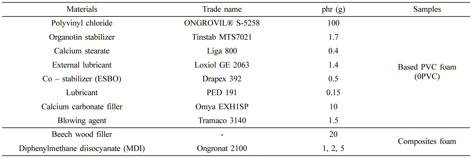
Materials and Method. The polymer matrix was polyvinyl chloride (PVC, K-value=58) provided by BorsodChem Zrt. In Table 1 all of the components and material types of the composites are summarized.
The natural filler used was beech wood flour having an average particle size of 200 to 300 µm. The L/D ratio of filler was 1.4. The wood flour was obtained at a local trader. To increase the adhesion between PVC and the natural filler, the natural filler was treated with 4,4'-diphenylmethane diisocyanate (MDI). The MDI was also provided by BorsodChem Zrt. The used quantities were 1, 2, 5phr (compared to the 20phr amount of the natural filler) respectively. The density of the MDI is 1.21 g/cm3. The foaming agent was a catalyzed azodicarbonamide, with a blowing temperature of 140oC.
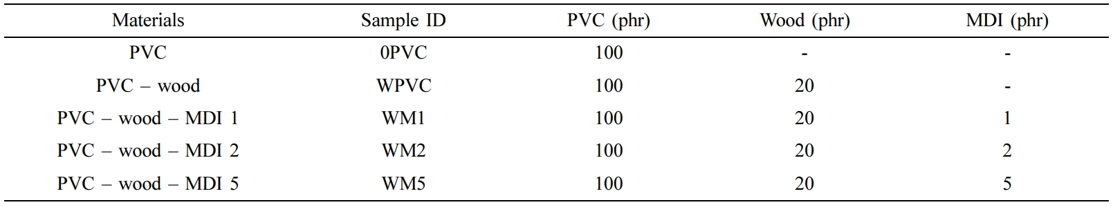
Sample Preparation and Production Conditions. In the first step the base PVC mixture was prepared, after this the wood flour and the surface treated wood flour filler was mixed in the matrix according to Table 2. The surface treatment of the natural additive was done by spraying it with MDI during continuous mixing. The mixtures were homogenized in a high-speed mixer – MTI20FU type 20l. Mixing was carried out to a temperature of 110°C and the cooling temperature was 40°C. The dry powder mixtures were processed on a Göttfert Extrusiometer 30 equipment. The extruder’s temperature variation from feeder to tool was between 175-190°C. The extruder’s tool was a wide slot tool with dimensions of 100×3mm. Pressed, compact samples were also prepared for analysis. Five different composites were made. The composition of each is shown in Table 2.
The powder mixture was rolled at 170°C using a Schwabenthan 150UL electrically heated roll mill. The rolled sheets were pressed using a Bürkle LA 160-type press at 175°C. The pressed thicknesses were 1 and 4 mm, respectively, at a pressure of about 100 bar.
Experimental Approach. Based on Archimedes’ principle, density measurements were carried out with an analytical balance. The dry and in water immersed masses were measured to calculate the density. The results of 3 samples per type were averaged.
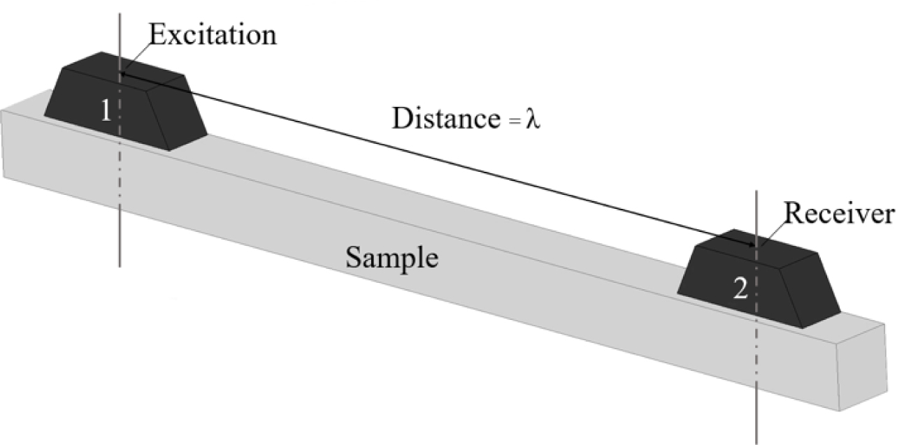
The ultrasonic characterization was carried out using a Fakopp Ultrasonic timer.21 The test is non-destructive, and it is an important tool for evaluating the structure of wood, veneer, wood panels, and concrete materials. The defect locations or cellular morphology of the wood, in this case of the wood composite, can be determined by the longitudinal ultrasound waves. The method is based on measuring the time of ultrasound wave propagation at a specified distance. Based on Figure 1, two identical piezoelectric transducers are connected to the material during the tests. A short ultrasonic pulse is generated by the electronic excitation of one of transmitters. The sound spreads in the material and reaches the second transmitter, which is used as a converter. The second signal from the receiver stops the timer.
The propagation time is displayed on the device’s screen in microseconds. From the ultrasound’s propagation time between the transmitter and receiver, the propagation speed can be determined by the following eq. (1):22
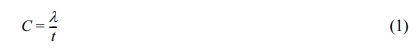
where: C – propagation speed [m/s], λ – distance between the transmitter and receiver [m] and, t – time [sec].
The modulus of elasticity is calculated from the ultrasound’s speed as follows:22
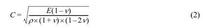
where: E – modulus of elasticity [Pa], ν – Poisson factor [-], and ρ – density [kg/m3].
According to the literature, the Poisson factor used for the pressed PVC/wood composites was 0.4, while for the foamed samples the Poisson factor was 0.3.23,24
The dynamic mechanical analysis (DMA) technique was used to check the results of the modulus calculated by ultrasonic measurements. The measurements were carried out using a Rheometric Scientific MK-III instrument in dual cantilever deformation mode. The deformation frequency was 1 Hz with less than 0.2% deformation. The heating rate was set to 2°C/min, and the temperature range was 20-100°C.
Bending tests, using an INSTRON 5566 type universal materials tester, were also carried out to verify the modulus. The bending type was three-point bending; the bending speed was 50mm/min; the support width was 80mm. The measured results of the 7 samples per type in machine and cross directions were averaged.
|
Figure 1 Set up of the ultrasonic measurement. |
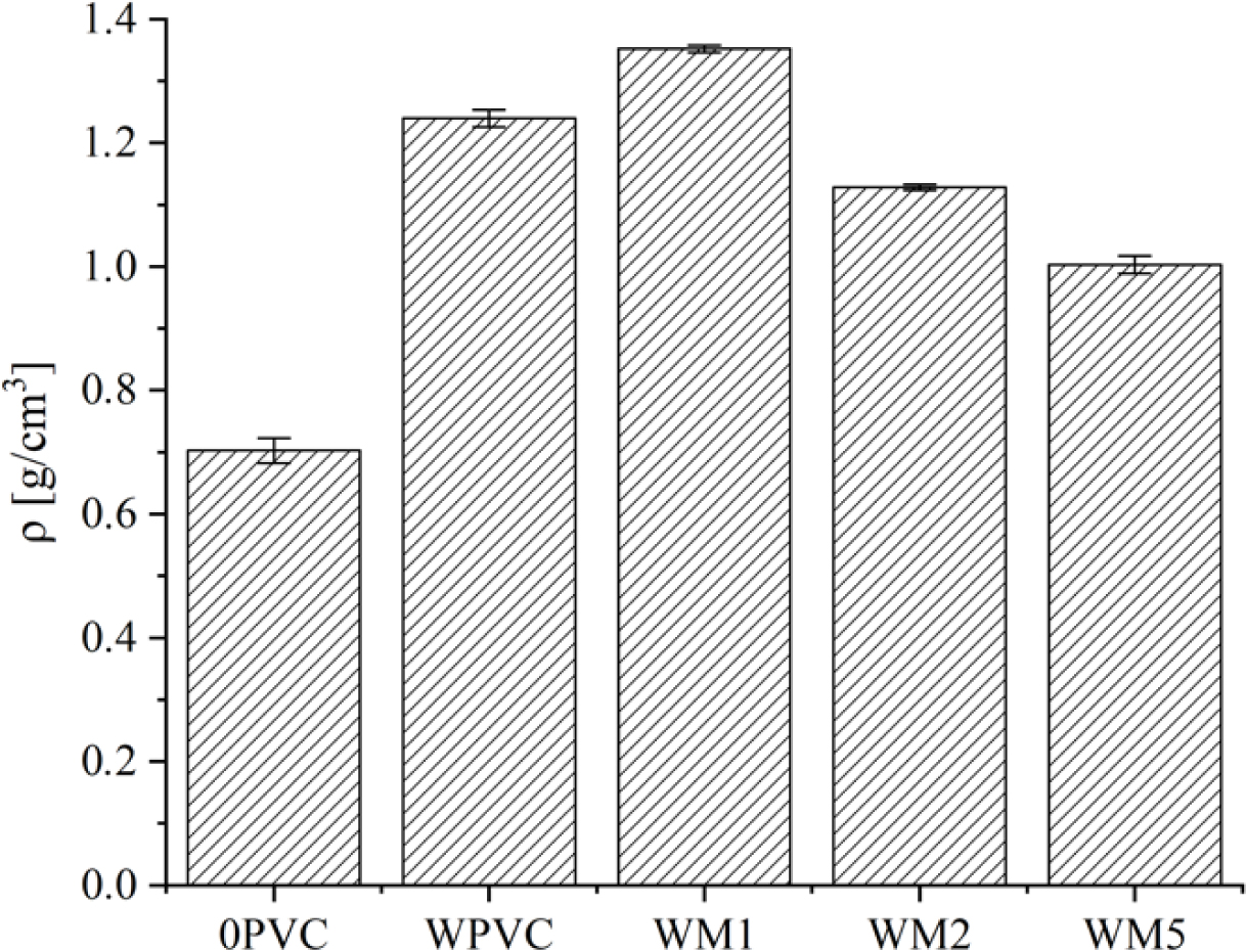
Density of Composites. Based on the density results (Figure 2), due to the compact density of wood flour, which is higher than the PVC’s (1.52 vs 1.4), the density of the composites initially increased. The density further increased by using MDI treatment. MDI primarily fills the pores of wood and creates better adhesion between the PVC and the wood flour. However, using higher amounts of MDI resulted in decreasing density, due to the lower density of MDI (compared to both PVC and wood). In addition, the formation of CO2—due to the small amount of moisture present in the composite—also lowered the density.
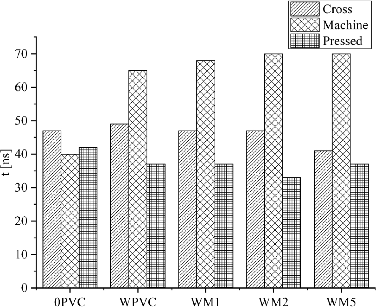
Ultrasonic Measurements. Ultrasonic measurements can be used to determine the propagation time of the ultrasound waves between the transmitter and the receiver.21 The measurement is easily performed on the surface of the samples with a minimum thickness of 4 mm. The ultrasound examination was performed in both cross (perpendicular to the manufacturing direction) and machine (manufacturing) directions. The propagation times of the measured ultrasounds are shown in Figure 3. Based on the differences of pressed and foamed samples, the effect of the structure and orientation of the reinforcing material was examined.
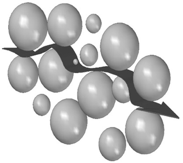
The foamed 0PVC samples showed no significant directional dependence. In the case of the foamed composites, the propagation time increased in the machine direction. However, orientation is introduced into the samples during extrusion, and, therefore, the reinforcing materials should be oriented in this direction. Since the solid matrix should propagate the waves more quickly, the results indicate that the natural fillers are present in high quantities in the cross direction. The dependence of the ultrasound propagation time suggests that the filler particles are strongly oriented, i.e. show material structure anisotropy. Due to the higher free volume of the PVC matrix (being an amorphous polymer) in the pressed samples compared to the composites, the ultrasound wave propagation speed is slower than the one with the cellulose-lignin wood structure incorporated what has reduced the free volume further stiffening the polymer chains.25 Therefore, the speed of ultrasound propagation in composites containing additives of natural origin is slightly faster than in the pure PVC. In addition, for foams the morphology of cells must be taken into account. Ultrasonic waves may be propagated in cell walls, as demonstrated in Figure 4. The waves have to travel a longer distance in the cell walls, than the straight line between the sonotrodes (excitation-receiver). The cells are not spherical in shape and are unevenly distributed, which also affects the propagation times.
From the results of the calculated ultrasonic propagation speeds of the pressed samples, the speed in the wood composites was higher than in the 0PVC sample. In the case of the foamed composites, the sample without filler had a faster propagation speed in the machine direction. Based on Figure 5, the propagation of the ultrasound in the machine direction indicates that the longitudinal sound waves actually take a longer path between the cells when compared to the cross direction. The ultrasound propagation time gets faster as the amount of MDI is increased in the cross direction. This anisotropic behavior is only observed in the natural additive filled composites.
The ultrasonic wave propagates faster in the wood than in air, and thus theoretically the moduli of the samples will also be higher than that of the 0PVC sample. The calculated moduli of the samples are shown in Figure 6. The reason for this higher moduli in the samples is that the density of the foams has increased with the addition of wood flour that increasing the materials amount. The beech wood we used had a substantially lower modulus than the base PVC, and therefore the propagation speed and modulus decreased. The increase in modulus shows a stronger connection between the filler and the matrix and the orientation of the extruded samples. Based on the results of calculated the moduli, the orientation of the reinforcing materials can be determined. The calculated moduli of wood filled foams are lower in the machine direction than the moduli for the other composites. In fact, the modulus of the pressed samples is also higher due to the density of the samples. In the case of pressed specimens, the orientation effects may be negligible.
A cross-section examination—at the edges and at the middle—of each composite sample was also made. Due to the width of the samples, the possible number of measurements was limited.
Figure 7 shows that the ultrasound wave propagates differently across the samples. In most cases the propagation speed was faster in the middle of the samples. Presumably, the distribution of fibers and foam cells also differs along a line probably due to the extrusion. These results are due to the shear conditions within the extruder.26 The cells were deformed at the edges of the samples. In the machine direction, this behavior was not observed, proving that the distribution of wood particles in the machine direction is more even.
To interpret the measurement results, measurements of unfilled PVC and neat beech wood were also performed. The results of the unfilled PVC sample showed an isotropic distribution in any direction. In the case of beech wood, the propagation speed was lower in the fiber than in the cross direction. As a result, the beech wood has a lower modulus and ultrasonic propagation speed than the PVC. Depending on the propagation rate, the modulus of the PVC was higher (595MPa) than the modulus of the wood (cross – 306MPa, fiber – 148MPa). Therefore, the propagation rate slows down when an ultrasonic wave reaches the wood particle. This also explains the results of the ultrasonic measurements presented above.
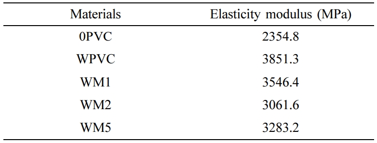
Modulus of Elasticity with DMA. The results of the ultrasonic modulus measurements were also compared with DMA measurements, and are presented in Table 3. The elastic modulus values were examined at room temperature (23±1°C).
The DMA measured approximately four times higher than previously, because—in the case of ultrasonic measurements—the deformation mode is longitudinal. In the case of bending, the modulus is always higher, but also depends on the foam geometry.
The 0PVC sample measurement had the lowest modulus. The content of the wood increased the modulus for all the wood composites.27 Compared to the WPVC sample, the modulus of the MDI containing composites decreased; this also shows the structure-modifying effect of MDI.
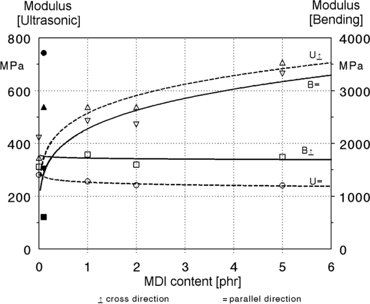
Modulus of Elasticity with Bending Tests. The ultrasonic propagation mostly depends on the modulus and the density of the materials. Therefore, if we calculate the results to the density of each mixture as a unit, that density being 1 g/cm3, the results can be compared with each other. In Figure 8 it can be seen that the calculated modulus from the speed of the ultrasound does not change longitudinally, but increases monotonically in the cross direction. Conversely, during the bending test, this monotonic increase for the samples in the machine direction is observed. The orientation of the natural additive can be determined if we take into account the L/D ratio of the wood flour using the results of the ultrasonic modulus increase in the cross direction and the results of the increase in the flexural modulus in the machine direction.28
|
Figure 2 Results of the density measurements. |
|
Figure 3 Propagation time results of all specimens. |
|
Figure 4 Ultrasonic wave propagation in the foamed samples (the spheres represent the cavities). |
|
Figure 5 Calculated speed of ultrasound waves for all specimens. |
|
Figure 6 Elastic moduli of all the specimens. |
|
Figure 7 Cross sectional measurement of the composites. |
|
Figure 8 Comparison of ultrasonic and flexural moduli mdi content. |
In this article, the moduli of the samples were determined by ultrasonic timer, DMA measurement, and bending tests. The measurements were already based on different measurement procedures, and therefore the orientation of the natural additives and the foam of all the structures could also be examined from the differences and similarities of the results. From the results of the ultrasonic measurements, the orientation of the reinforcing materials in the composites could be determined. In the case of compression molded samples, it was observed that the modulus values of the samples increase (measured by ultrasonic) until 5phr MDI application. MDI improves the connection between the filler and the matrix, which further increased the modulus of the composites (for samples WM1, WM2). In the case of composite MDI 5, the layer of isocyanate is thicker at the surface of the wood particle, which by its lower modulus hinders the transfer of longitudinal waves between the particles and the matrix, artificially lowering the observed modulus. For the foamed samples, the addition of MDI usually lowered the ultrasonic observed modulus in the machine direction. Due to the complicated path taken by the sound waves, the effect of the lower modulus MDI was more pronounced. In the case of all the foamed composites, surprisingly, a lower machine direction modulus was measured compared to the cross direction. This phenomenon is supported by the measurement results of pure beech wood and PVC. From the results of both ultrasonic measurement and the bending test, it can be concluded that the orientation is in the machine direction in the composite. Mechanical testing always showed a higher modulus in the machine direction, and, therefore, this odd behavior can be explained by the way ultrasound propagates and interacts with the material.
- 1. Mills, N. Micromechanics of Open-cell Foams. In Polymer Foams Handbook; Rapra Technology: United Kingdom, 2007; pp 147-175.
-

- 2. Singha, A. S.; Thakur, V. K. Mechanical Properties of Natural Fibre Reinforced Polymer Composites. Bull. Mater. Sci. 2008, 31, 791-799.
-
- 3. Peretomode, T. M.; Eboibi, B. E.; Fakrogha, J. J. Preparation and Characterization of Wood Dust Natural Fiber Re-enforced Polymer Composite. J. Appl. Sci. Environ. Manage. 2019, 23, 1103.
-
- 4. Mohammad Taheri, H.; Behravesh, A. H.; Kargar, M. A Modular Extrusion Die Design to Produce Continuous Glass Fibers Reinforced PVC-wood Composite Profiles. Polym. Compos. 2016, 39, 2268-2276.
-
- 5. Nabi Saheb, D.; Jog, J. P. Natural Fiber Polymer Composites: A Review. Adv. Polym. Techn. 1999, 18, 351-363.
- 6. Bakar, A. A.; Hassan, A.; Yusof, A. F. M. Effect of Oil Palm Empty Fruit Bunch and Acrylic Impact Modifier on Mechanical Properties and Processability of Unplasticized Poly(Vinyl Chloride) Composites. Polym.-Plasti. Tech. Eng. 2005, 44, 1125-1137.
-
- 7. Hong, J.; Kim, D. S. Effects of Coupling Agents and Nanosilicas on the Physical Properties of PVC/Wood Flour Composites. Polym. Korea 2015, 39, 643-648.
-
- 8. Jha, K.; Kataria, R.; Verma, J.; Pradhan, S. Potential Biodegradable Matrices and Fiber Treatment for Green Composites: A Review. AIMS Mater. Sci. 2019, 6, 119-138.
-
- 9. Arjmand, F.; Barmar, M.; Barikani, M. Isocyanate Modification of Wood Fiber in Enhancing the Performance of Its Composites with High Density Polyethylene. Polym. from Renew. Resour. 2012, 3, 43-60.
-
- 10. Abu-Zahra, N. H.; Seth, A. In-process Density Control of Extruded Foam PVC Using Wavelet Packet Analysis of Ultrasound Waves. Mechatronics 2002, 12, 1083-1095.
-
- 11. Abu-Zahra, N. H. Measuring Melt Density in Polymer Extrusion Processes Using Shear Ultrasound Waves. Int. J. Adv. Manuf. Tech. 2004, 24, 661-666.
-
- 12. Moon, J.; Kwak, S. B.; Lee, J. Y.; Kim, D.; Ha, J. U.; Oh, J. S. Synthesis of Polyurethane Foam from Ultrasonically Decrosslinked Automotive Seat Cushions. J. Waste Manag. 2019, 85, 557-562.
-
- 13. Fellah, Z. E. A.; Mitri, F. G.; Fellah, M.; Ogam, E.; Depollier, C. Ultrasonic Characterization of Porous Absorbing Materials: Inverse Problem. J. Sound VIB. 2007, 302, 746-759.
-
- 14. Xia, N.; Zhao, P.; Kuang, T.; Zhao, Y.; Zhang, J.; Fu, J. Nondestructive Measurement of Layer Thickness in Water-assisted Coinjection-molded Product by Ultrasonic Technology. J. Appl. Polym. Sci. 2018, 135, 46540.
-
- 15. Michaeli, W.; Starke, C. Ultrasonic Investigations of the Thermoplastics Injection Moulding Process. Polym. Test. 2005, 24, 205-209.
-
- 16. Zhao, P.; Peng, Y.; Yang, W.; Fu, J.; Turng, L.-S. Crystallization Measurements via Ultrasonic Velocity: Study of Poly(Lactic Acid) Parts. J. Polym. Sci. Polym. Phys. 2015, 53, 700-708.
-
- 17. Zhao, P.; Zhao, Y.; Kharbas, H.; Zhang, J.; Wu, T.; Yang, W.; Turng, L.-S. In-situ Ultrasonic Characterization of Microcellular Injection Molding. J. Mater. Process. Technol. 2019, 270, 254-264.
-
- 18. Ghose, S.; Isayev, A. I. Recycling of Unfilled Polyurethane Rubber Using High-power Ultrasound. J. Appl. Polym. Sci. 2003, 88, 980-989.
-
- 19. Ayrault, C.; Moussatov, A.; Castagnède, B.; Lafarge, D. Ultrasonic Characterization of Plastic Foams via Measurements with Static Pressure Variations. Appl. Phys. Lett., 1999, 74, 3224-3226.
-
- 20. Fellah, Z. E. A.; Depollier, C.; Berger, S.; Lauriks, W.; Trompette, P.; Chapelon, J.-Y. Determination of Transport Parameters in Air-saturated Porous Materials via Reflected Ultrasonic Waves. J. Acoust. Soc. Am. 2004, 114, 2561.
-
- 21. Fakopp. User’s Guide Fakopp Ultrasonic Timer, Fakopp Bt., 2020; pp 2-9.
- 22. György, C.; Mariann, K. Anyagvizsgálati Praktikum; Sunplant: Miskolc, Hungary, 2008; pp 191-193.
- 23. Polymer Properties Database, Available: http://polymerdatabase. com/polymer physics/Poisson Table2.html. (accessed 2020. 07.01).
- 24. Kljak, J.; Brezović, M. Influence of Plywood Structure on Sandwich Panel Properties: Variability of Veneer Thickness Ratio. Wood Res. 2007, 52, 77-88.
- 25. Mengeloglu, F.; Matuana, L. M. Mechanical Properties of Extrusion-foamed Rigid PVC/Wood-flour Composites. J. Vinyl Addit. Technol. 2003, 9, 26-31.
-
- 26. Wang, M.; Liu, J.; Hu, J.; Zhou, N. The Effect of Processing Parameters on Cell Structure and Mechanical Properties of Extrusion-foamed Poly(Vinyl Chloride) Sheets. J. Vinyl Addit. Technol. 2014, 22, 377-383.
-
- 27. Shah, B. L.; Matuana, L. M.; Heiden, P. A. Novel Coupling Agents for PVC/Wood-flour Composites. J. Vinyl Addit. Technol. 2005, 11, 160-165.
-
- 28. Khonsari, A.; Taghiyari, H. R.; Karimi, A.; Tajvidi, M. Study on the Effects of Wood Flour Geometry on Physical and Mechanical Properties of Wood-plastic Composites. Maderas-Cienc Technol. 2015, 17.
-

- Polymer(Korea) 폴리머
- Frequency : Bimonthly(odd)
ISSN 0379-153X(Print)
ISSN 2234-8077(Online)
Abbr. Polym. Korea - 2023 Impact Factor : 0.4
- Indexed in SCIE
 This Article
-
2021; 45(1): 31-38
Published online Jan 25, 2021
- 10.7317/pk.2021.45.1.31
- Received on Jul 4, 2020
- Revised on Sep 21, 2020
- Accepted on Oct 5, 2020
Services
- Full Text PDF
- Abstract
- ToC
- Acknowledgements
Introduction
Experimental
Results and Discussion
Conclusions
- References
Shared
Correspondence to
- Krisztina Román
-
Institute of Ceramic and Polymer Engineering, University of Miskolc, Miskolc-Egyetemváros St., 3515, Hungary
- E-mail: polkrisz@uni-miskolc.hu
- ORCID:
0000-0002-2965-0061
Hyecheon Building(Room 601), #354, Gangnam-Daero, Gangnam-Gu, Seoul 06242, Korea
TEL : 82-2-568-3860, 561-5203, 569-3860 FAX : 82-2553-6938 E-mail: polymer@polymer.or.kr