


- Studies on the Preparation and Characterization of Poly(vinyl alcohol-co-styrenesulfonic acid)-Based Proton Exchange Membranes for Direct Methanol Fuel Cell
Rikarani R. Choudhury and Jaydevsinh M. Gohil*, **,†

Laboratory for Advanced Research in Polymeric Materials (LARPM), School for Advanced Research in Petrochemicals (SARP), Central Institute of Petrochemicals Engineering & Technology (CIPET), Bhubaneswar-751024, Odisha, India
*Advanced Polymer Design and Development Research Laboratory (APDDRL), School for Advanced Research in Petrochemicals (SARP), Central Institute of Petrochemicals Engineering & Technology (CIPET), Bengaluru-562149, Karnataka, India
**Advanced Research School for Technology and Product Simulation (ARSTPS), School for Advanced Research in Petrochemicals (SARP), Central Institute of Petrochemicals Engineering and Technology (CIPET), Chennai-600032, Tamil Nadu, India- 직접메탄올 연료전지를 위한 Poly(vinyl alcohol-co-styrenesulfonic acid) 기반의 양성자 교환막의 제법 및 특성 연구
Reproduction, stored in a retrieval system, or transmitted in any form of any part of this publication is permitted only by written permission from the Polymer Society of Korea.
Development of proton conducting membrane electrolyte is one of the most important research area within the domain of direct methanol fuel cells (DMFCs). This study reports the preparation of glutaraldehyde-crosslinked poly(vinyl alcohol-co-styrenesulfonic acid) proton exchange membrane (PEM) for DMFC. In order to understand the effect of the extent of crosslinking on the PEM properties, varying concentration of glutaraldehyde was used. Key properties of PEMs such as water uptake, swelling behavior, ion-exchange capacity, proton conductivity, and methanol permeability were thoroughly analyzed. PEM formed using 0.5 M glutaraldehyde solution resulted in a crosslinked PEM with the moderate properties, such as swelling, water uptake, proton conductivity and mechanical strength, along with the exhibition of high proton conductivity and lower methanol permeability compared to commercial Nafion-117. In addition, optimized PEM produced a peak power density of 58 W/m2 at a current density of 300 A/m2, when DMFC fed with 2 M methanol solution at 60 °C.
This paper reports poly(vinyl alcohol-co-styrenesulfonic acid) (PVA-co-SSA) based proton exchange membrane made by solution-casting method using water as solvent. Proton exchange membrane (PEM) was crosslinked through acetalization reaction. Due to film forming ability of PVA-co-SSA, the resulting PEM was quite flexible and membranes exhibited lower methanol permeability than Nafion-117. PEM crosslinked using lower concentration of glutaraldehyde showed good performance in direct methanol fuel cell which was moderately comparable to Nafion-117.
Keywords: poly(vinyl alcohol-co-styrenesulfonic acid), glutaraldehyde, crosslinking, direct methanol fuel cell, proton exchange membrane, methanol permeability.
Authors (Gohil and Choudhury) grateful to Science and Engineering Research Board, New Delhi, for Early Career Research Award, Project No.: ECR/2017/000028.
The authors declare that there is no conflict of interest.
Information related to the swelling (thickness and area swelling) of PEMs, impedance spectra of PEM-N, PEM-0.5G, PEM-1G and PEM-2G, and proton transport mechanism through PEM is given. The materials are available via the Internet at http://journal.polymer-korea.or.kr.
PK_2022_046_05_627_Supporting_Information_template.pdf (243 kb)
Supplementary Information
Use of renewable energy sources to meet the requirements of everyday energy demand has been increasing in the present scenario. One of the green energy production means, which has attracted many researchers and industries throughout the word, is the fuel cell (FC) technology. Proton exchange membrane FC (PEMFC), including direct methanol FC (DMFC), is one of the most promising sustainable energy sources due to its simplicity and its potentiality for stationary and mobile power generation applications.1-3 A FC that utilizes methanol (MeOH) as a fuel for electricity generation is known as a DMFC. In a DMFC, MeOH solution is fed to the anode side, while air or oxygen gas is pumped to the cathode. Methanol get oxidized at the catalyst surface at the anode and produces electrons and protons. The protons conduct via the proton exchange membrane (PEM) from the anode chamber to the cathode chamber, while electrons flow through the outer circuit and generates electricity. At the cathode, reduction of oxygen (O2) in presence of protons generates water. The PEM is one of the crucial functional components of a DMFC. Polymers used for PEMs’ fabrication should have high proton conductivity, mechanochemical stability and low MeOH permeability. The PEMs or ion-exchange membranes can be categorized as homogeneous,4-8 composite,9-13 nanocomposite,14-21 metal-organic-framework (MOF),22 blend,23-25 heterogeneous26-28 or pore filled membranes.29-31
Usually, polymer electrolytes used for PEMs’ preparation contain strong cation-exchange groups, such as -SO3H, -COOH and -H3PO4, which are directly attached to the polymer chains.32-34 Poly(vinyl alcohol) (PVA) and sulfonated polymers-based polyelectrolytes are promising materials for PEMs for DMFC application. PVA-based copolymers have been extensively studied for preparation various ionic membrane(s) for FCs applications,35 as PVA possesses film forming, water uptake and crosslinking capabilities, and also offers low methanol permeability.36-41 On the other hand, sulfonated polymers, such as polystyrene sulfonic acid (PSSA), have high proton conductivities;42 however, as such, their application in PEM fabrication is limited due to their water solubility and lack of film forming ability. Hence, for the use of such polymers in PEMs’ fabrication, a crosslinking and copolymerization method has been adopted. Membranes, based on the blends of PVA and PSSA, have been extensively studied in order to optimize their electrochemical properties, MeOH permeability and DMFC performance.23,43,44 In addition, use of copolymers, such as poly(vinyl alcohol-b-vinyl benzene trimethyl ammonium chloride) (PVA-b-PVBTAC),45 poly(vinyl alcohol-b-styrene sulfonic acid)8 and poly(vinyl alcohol-co-2-methyl-1-propanesulfonic acid),41 have been reported for the preparation of PEMs for PEMFC applications. Higa et al.3 described a PEM-based on block copolymer of poly(vinyl alcohol-b-styrene sulfonic acid) (PVA-b-PSSA) that contained 93 mole% of PVA-segment and 7 mole% of PSSA-segment, and crosslinked using glutaraldehyde (GA). It was found that enhancing the GA concentration caused in reduction in the protons conductivity as well as the methanol permeability of PEMs based on PVA-b-PSSA. In another work, Higa et al. used GA for the crosslinking of PVA-b-PVBTAC copolymer, for the development of PEM having low MeOH permeability.4
The preparation of block copolymers such as PVA-b-PSSA and PVA-b-PVBTAC involves multiple steps and required very stringent polymerization conditions to obtain desired molecular weight. Beside block copolymers, researchers used blend of PVA and PSSA for preparation of PEMs,23,44 in such membranes PSSA exist as dispersed phase through hydrogen bonding into crosslinked PVA matrix. Application of such membrane in DMFC at the beginning exhibited good performance, since, PSSA is highly water soluble hence leaching from crosslinked PVA matrix cannot be ruled out. This research paper discusses the preparation of homogeneous PEMs, using poly(vinyl alcohol-co-styrenesulfonic acid) (PVA-co-SSA), which was synthesized by simple free-radical polymerization mechanism as reported in.8 This study explores the use of this polymer (PVA-co-SSA) for preparation PEM, and for that copolymer has been crosslinked using simple acetal linkage formation by room temperature reaction between glutaraldehyde and hydroxyl groups of PVA-co-PSSA. Crosslinking strategy was used to impede dissolution of PEMs. It is expected that the use of this PVA based copolymer for PEM preparation would decrease membrane swelling and MeOH permeability. As PVA unit in copolymer is expected to exclude MeOH, while SSA in PVA-co-SSA acts as proton transfer site. Since, this copolymer is highly hydrophilic, resulting PEMs structure inherently hold more water molecules compared to Nafion membrane at temperature >80 °C and hence, will exhibit more proton conductivity. Hence to study these hypothesis, effect of crosslinking on the fabricated PEMs’ physicochemical and electrochemical characteristics as well as the DMFC performance are presented in this paper.
Materials. The copolymer, PVA-co-SSA having M̅w of 270926 and polydispersity index of 2.84 was previously prepared in the laboratory is reported in.8 Standard anode and cathode gas diffusion electrodes (containing 0.5 mg/cm2 of 60:40 (wt:wt) Pt:C and 0.5 mg/cm2 of 60/40 (wt/wt) Pt-Ru:C catalyst, respectively), gaskets based on Teflon-coated fiber glass (having thicknesses of 0.22 and 0.1 mm for anode and cathode, respectively), and Nafion-117 membrane were procured from Sai Energy Fuel Cell Pvt. Ltd., India. Aqueous solution (25 wt%) of Glutaraldehyde (GA) (Grade-II) was obtained from Sigma-Aldrich, India. Hydrochloric acid (HCl) (35% Pure, AR), Sodium chloride (NaCl) (LR grade) and sodium sulfate (LR grade) were obtained from HiMedia Laboratories Pvt. Ltd., India. Sodium hydroxide (Extra Pure) was bought from Sisco Research Laboratories, India. Deionized (DI) water was produced using Elix® Millipore system (France), and was used for all the experiments.
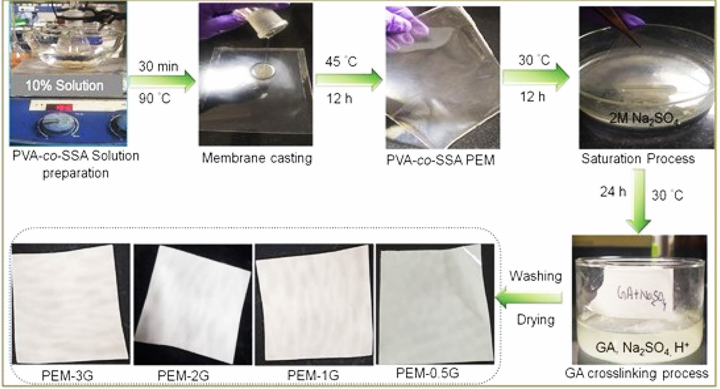
Preparation of Homogeneous Membranes Based on PVA-co-SSA. An aqueous solution of PVA-co-SSA (10% w/v) was prepared in distilled water by heating at 80 ºC for 30 min., followed by cooling at room temperature (25 ºC). Membrane of about 160-180 µm thicknesses were casted on the flexi glass plates and dried in hot air oven at 45 °C for 12 h. Dried membranes were then kept in sodium sulfate (Na2SO4) saturated solution (2 mol/L) for 12 h to form condensed (shrinked) PEM; after that, all the membranes were immersed into varying concentrations of glutaraldehyde (GA) solutions (i.e., 0.5 M, 1 M, 2 M and 3 M), containing 2 M Na2SO4 under acidic condition (pH~5) for 24 h to induce crosslinking of membranes.23,46 The corresponding crosslinked membranes have been abbreviated as PEM-0.5G, PEM-1G, PEM-2G and PEM-3G, respectively. Finally, the crosslinked PEMs were washed with distilled water to remove excess GA, dried in hot air oven at 45 ºC, and stored in a desiccator for further studies and characterizations. A schematic of the membrane preparation process has been shown in the Figure 1.
Characterization of PEMs. Fourier-transform infrared spectroscopy (FTIR, Nicolet 6700, Smart Orbit, USA) in attenuated total reflection (ATR) mode, was adopted to scan membrane-samples in the wavelength range of 400 to 4000 cm-1 at 5 cm-1 resolutions. Thermal stability of the PEMs was evaluated by thermo gravimetric analysis (TGA) (Q50, TA Instrument, USA) at a heating rate of 10 °C/min. X-ray diffraction (XRD-7000, Shimadzu, Japan) analysis was performed in a 2θ range of 5-90°. Surface morphology was evaluated by Field-emission gun scanning electron microscope (FEG-SEM) (GeminiSEM 300, ZEISS, Germany) in the SE mode. Before FEG-SEM analysis, the membrane-samples were sputter coated with gold-palladium, using Plasma Sputtering machine (SC7620). For cross-sectional surface examination, PEM samples were prepared by fracturing in liquid nitrogen. Membrane-samples (10 cm×2 cm) were fixed between two grips of Universal Testing Machine (UTM) (Instron 3382, UK) with 1 kN load cell and tensile strengths were measured at a crosshead speed of 10 mm/min. Stress-strain curves were recoded automatically using Blue Hill. A minimum of three samples were tested under the same condition, and the average results have been reported. Static contact angles of membrane surfaces were measured using Phoneix system (PHX300, SEO, South Korea) by employing distilled water droplet as a contacting liquid onto the surface of that membrane (fixed to the flat glass surface by double sided tape).
Evaluation of Swelling Properties: For this purpose, membrane-samples of about 7 cm×7 cm were first deep into DI-water, maintained at 25, 60, 70, and 80 oC. After 24 h, the swollen membrane-samples were taken out, wiped with tissue paper to absorb adhered water from the surface of membrane, and the wet weight of the specimens (PEMWSM) were recorded using digital balance. Before drying, thicknesses (PEMTSM) and areas (PEMASM) of the swollen membranes were measured. Subsequently, the membrane-samples were dried at 45 oC in hot air oven for 24 h, and the dry membrane weights (PEMWDM) and thicknesses (PEMTDM) were recorded. Finally, water uptake (%), membrane thickness swelling (SWLT, %) and membrane area swelling (SWLA, %) were calculated using the eqs. (1), (2) and (3), respectively, and the average value of three samples was reported.
Determination of Ion-exchange Capacity and Proton Conductivity. The membrane-specimens were kept in HCl solutions (1 mol/L) for 12 h, followed by washing with DI-water. The membranes were then deep into NaCl solution (1 mol/L) for 1 h (which resulted in conversion to Na+ form), and subsequently rinsed with DI water. Finally, the PEMs in the H+ form was immersed in NaCl solutions (0.1 mol/L) for 24 h, and the liberated HCl in solution for each membrane was estimated by titration against NaOH solution (0.1 mol/L). The IEC was determined using the eq. (4).47
where, VNaOH denotes the volume of NaOH consumed during the titration (mL), NNaOHrepresents the normality of NaOH solution, and PEMDWindicates the dry weight of membrane (g).
For protons conductivity measurement, the PEM test samples were first activated by keeping in HCl solution (0.1 mol/L) for 1 h. The proton conductivities of the fully-hydrated PEMs were analyzed by four-probe electrochemical impedance spectroscopy (EIS) (PARSTAT MC-1000, USA) method, by scanning the samples over an AC frequency span of 1 Hz to 1 MHz at a voltage magnitude of 50 mV. Proton conductivities of PEMs were determined using the eq. (5).48
where, σPEM is the proton conductivity (S/cm), and lelectrode, PEMR, PEMd and PEMT denote the distance between the two electrodes (cm), measured impedance of the PEM (Ω), width of the membrane (cm), and thickness of the membrane (cm), respectively.
Evaluation of MeOH Permeability and Selectivity. A diffusion-cell consisting of glass having two cell compartments as described in,49 was used to study the MeOH permeability (PPEM) of the membrane-samples. Test membrane sample(s) was placed between two compartments along with appropriate rubber gaskets; and the system was clamped to ensure leakproof. The compartments (A) and (B) were filled with MeOH solution (2 mol/L) and DI water respectively, and continuously stirred at 25 °C for 12 h. After that to evaluate any MeOH transport from the feed compartment-A to the permeate compartment-B through PEM, the sample solution from the feed-chamber and the permeate-chamber were collected, and the concentration of MeOH was determined by gas chromatography mass spectroscopy (GC-MS) (7000D Triple Quadrupole, Agilent, USA), and finally the MeOH permeability was calculated using eq. (6).
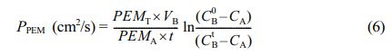
where, PM indicates the PEM MeOH permeability (cm2/s) of, PEMT represents the membrane thickness (cm), VB is the volume of solution in the chamber-B (cm3), PEMA denotes the active area of PEM (cm2), CB0 and CBt are the measured concentrations (mol/L) of MeOH in compartment-B at the beginning of experiment (t =0) and after time t (s) respectively. CA is the MeOH concentration (mol/L) of compartment-A solution.
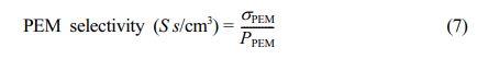
The membrane selectivity was evaluated by dividing proton conductivity (σPEM) by permeability of MeOH (PM), using the eq. (7).
MEA Preparation and Single-cell Performance in DMFC. Single cell DMFC stack was assembled using membrane-electrode-assemblies (MEAs). Typically, MEA was constructed by keeping a PEM between the catalyst coated anode- and cathode-gas diffusion electrodes (commercial standard electrodes), and the sandwich structure was gently pressed (applying only platen holding pressure) using hot press (HP 80 T, Neoplast Engineering, India) at about 55 °C. For measurement of polarization curve (I-V) a FC stack was connected to DMFC test station (WonATech, Korea). Anode and cathode compartments of cell was constantly fed with 2 M MeOH solution (at flow rate of 2-10 mL/min) and O2(g) respectively, and temperature of the FC stack compartments was maintained at 60 °C through PID controller. The draw current of the cell was increased step wise and resulting cell potential was recorded, before collecting the I-V data, a FC was run for at least 30 min. During data collection, at each preset current density, FC was run for at least 5 min to get stabilized cell potential value.
|
Figure 1 Schematic shows preparation of homogeneous PEMs based on PVA-co-SSA/GA and photographs of the membranes. |
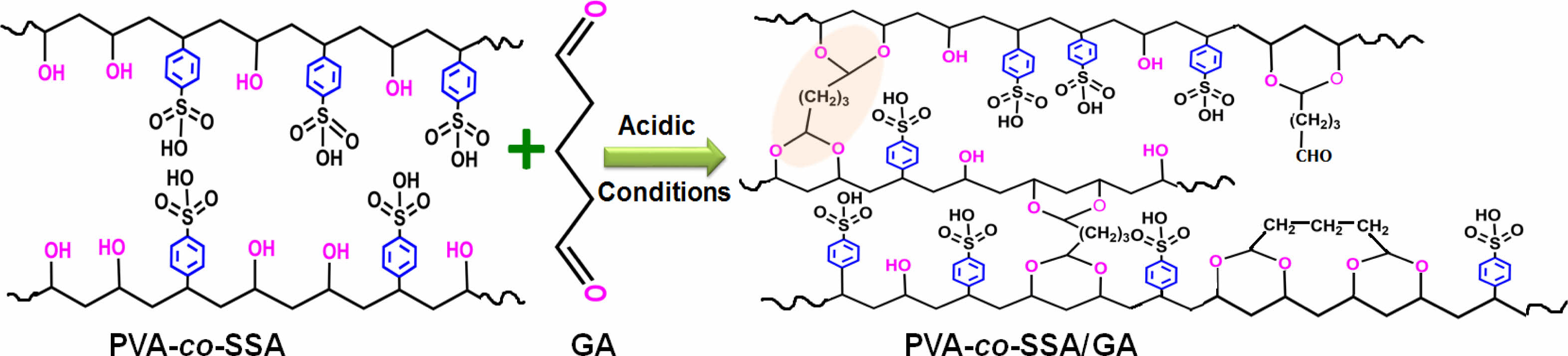
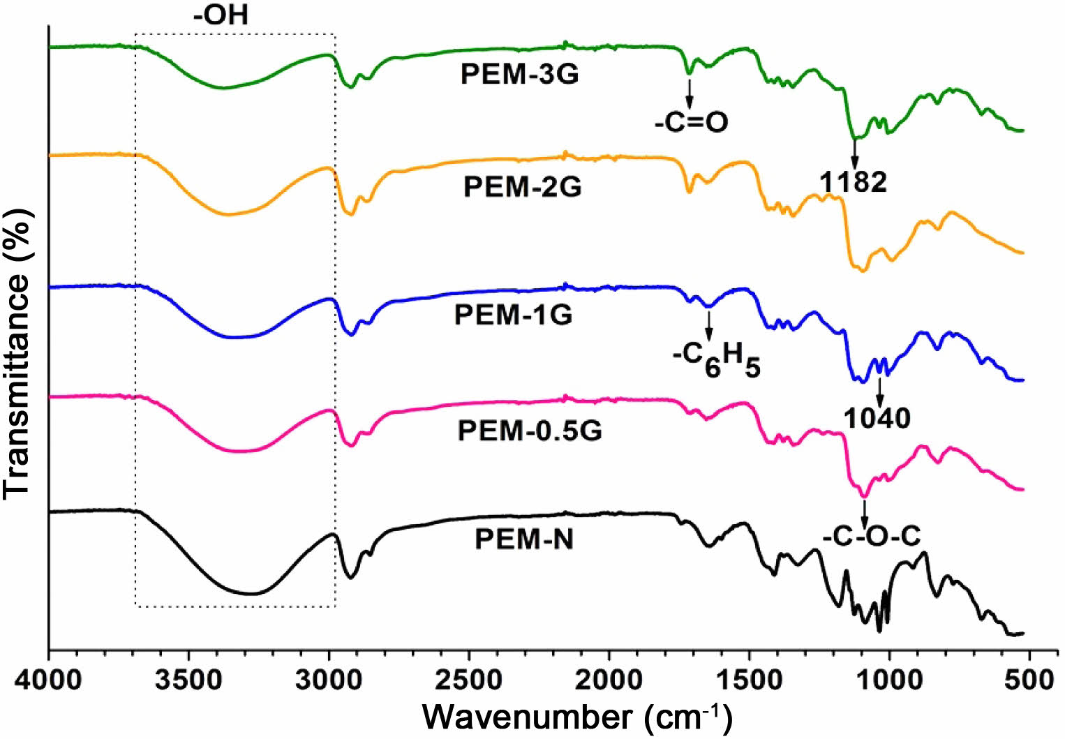
FTIR Characteristics of Homogeneous PEMs. The repeating units of PVA-co-SSA contain pedant hydroxyl (-OH) and sulfonic acid (-SO3H) groups. Use of a solution casting technique resulted in the formation of homogeneous PEMs (photographs of the casted membranes are shown in Figure 1), having dry thickness of about 160-180 µm. Further, to provide the dimensional stability and to constrain the permeability of MeOH permeability, it is required to crosslink the polymer matrix of PEM. Since GA is a very versatile crosslinker for PVA-based polymers, to examine the effect of the degree of crosslinking, dried PEMs were crosslinked by dipping them into a saturated Na2SO4 solution, containing different amount of GA. It is a well-known fact that GA induces crosslinking by acetal linkage formation, as shown in Figure 2. The IR spectra of the neat (uncrosslinked, PEM-N prepared without use of GA), and the crosslinked PEMs (prepared using varying concentration GA), based on PVA-co-SSA, are presented in Figure 3.
Uncrosslinked neat PEM-N exhibited prominent peaks at 3270 cm-1 which is attributed to ν(OH) from vinyl alcohol groups, and peaks appeared at 1182 cm-1 and 1040 cm-1 can be assigned to νas(O=S=O) and νs(O=S=O) groups representing styrenesulfonic acid constituents of the copolymers. The observed ν(C=C) in the range of 1411-1653 cm-1 is ascribed to the aromatic ring (substituted with -SO3H groups).8 Upon crosslinking, GA reacted with -OH groups of vinyl alcohol and formed acetal linkages (-C-O-C-), resulted in the construction of network structure (Figure2). In the crosslinked PEMs, the bands appearance of ν(C=O) at 1709 cm-1 and ν(-C-O-C-) at 1092 cm-1 confirmed the acetal formation.29,50 The increase in crosslink density with increase in GA concentration is expected to attribute in reduction in the peak intensity of ν(OH) at 3270 cm-1 and increasing the band intensity of ν(C=O) at 1709 cm-1. Crosslink density can be defined as “the density of chains or segments that connect two infinite parts of the polymer network”.51 Crosslinking alters the physicochemical structure of a PEMs. Herein, the crosslinking of PEMs through acetal formation led to the reduction in H-bonding (disorder in polymer molecules) that is clearly seen from the decrease in the broadness of the FTIR-peak at 3270 cm-1, and the peak in the range of 1000-1420 cm-1 attributed to hydroxy groups.
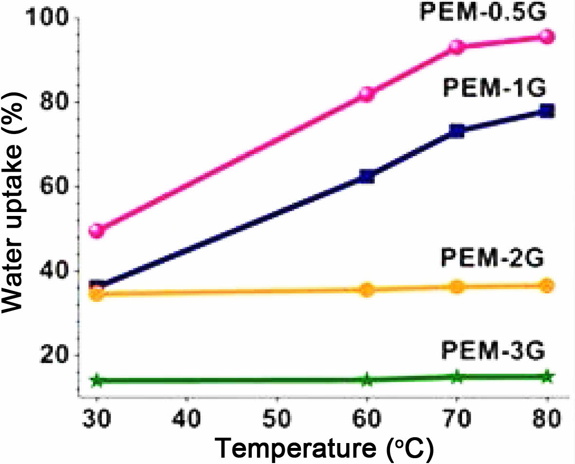
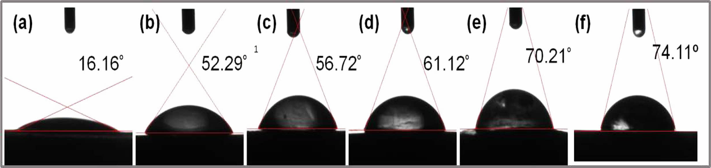
Water Uptake, Swelling and Hydrophilicity. Interaction of solvent molecules, such as water, with polyelectrolyte, i.e., PVA-co-SSA, results in a change in the intermolecular attraction between the polymer molecules and generation of intramolecular interactions between the polymer and water. Therefore, sorption of water molecules, owing to the formation of H-bonding, results in polymer solvation. Crosslinking of polymer matrix physically confines the polymer i.e. PEM matrix and increases the volume-fraction of the polymers in swollen mass,29 and thereby induces more dimensional stability. Water uptake indicates the affinity of polymers towards solvent, and indirectly hints towards the extent of crosslink density of the PEM matrix. Water uptake and swelling properties of the PEMs at varying concentrations of GA has been shown in Figure 4. It should be noted that neat PEM-N was get soluble in water and hence, it was not possible to measure swelling properties. For crosslinked PEMs, the observed trend in water uptake clearly indicates that as the GA concentration increased, the water uptake of the crosslinked PEMs gets diminished. Also, it was observed that values of water uptake for PEMs immersed in hot water (80 ºC) were higher than those kept in water at room temperature (30 ºC). For instance, PEM-0.5G, PEM-1G, PEM-2G and PEM-3G exhibited water uptake of 49.47, 36, 34, and 14%, respectively, owing to the increase in crosslink density of the PEMs as well as the reduction in the hydrogen bonding sites within the PEMs. In case of % swelling, a similar trend was observed (supporting information Figure S1(a) and S1(c)). It was realized that as the temperature of water increased, the swelling of PEMs increased, which resulted in changes in thickness (SWLT) and area (SWLA) of PEM-0.5G, PEM-1G, PEM-2G and PEM-3G. This observation can be attributed to the fact that at lower crosslink density of PEMs. At low crosslink density (at concentration of GA) as well as at high temperature of the solvent (water), the polymer chains get relaxed and allows for more sorption of water molecules, which ultimately resulted in more swelling of PEMs. For example, at 30 ºC, PEM-0.5G showed 38.7% and 15.5% thickness and area swelling, respectively, which got further increased to 49.32% and 69%, respectively, at 80 ºC. Overall, water temperature showed more pronounced effect on swelling and water uptake properties of PEMs crosslinked at lower concentration of GA than PEMs obtained using high concentration of GA. For instance, PEM-3G and PEM-2G, highly crosslinked network structure that restricted the relaxation of polymer chains, resulted in lower water uptake and % swelling. Another important property of PEM is its hydrophilicity, which can be measured from the values of contact angle of water on the PEM surface. Reaction of GA with the hydroxyl (-OH) groups of the PVA-co-SSA in the PEM matrix led to the formation acetal linkages, and thereby resulted in a decrease in the available hydroxide groups on the surface and bulk of the PEM, leading to reduced hydrophilicity. Usually, crosslinking increases water contact angle of PEM when a hydrophilic polymer i.e. PEM is chemically crosslinked. Values of static contact angle of water droplets on the PEM surfaces have been shown in Figure 5. Because of numerous H-bonding sites present within the neat PEM, a water droplet easily spreads on the surface of the membrane and exhibits hydrophilic characteristics (i.e., a contact angle of 16.16º); while, PEMs obtained by GA-crosslinking exhibited contact angle values of 52.29, 56.72, 61.12, and 70.21º for PEM-0.5G, PEM-1G, PEM-2G and PEM-3G, respectively. It must also be noted here that all of the fabricated membranes showed lower contact angle values compared to Nafion-117 (i.e., 74.11º), when measured under similar conditions.
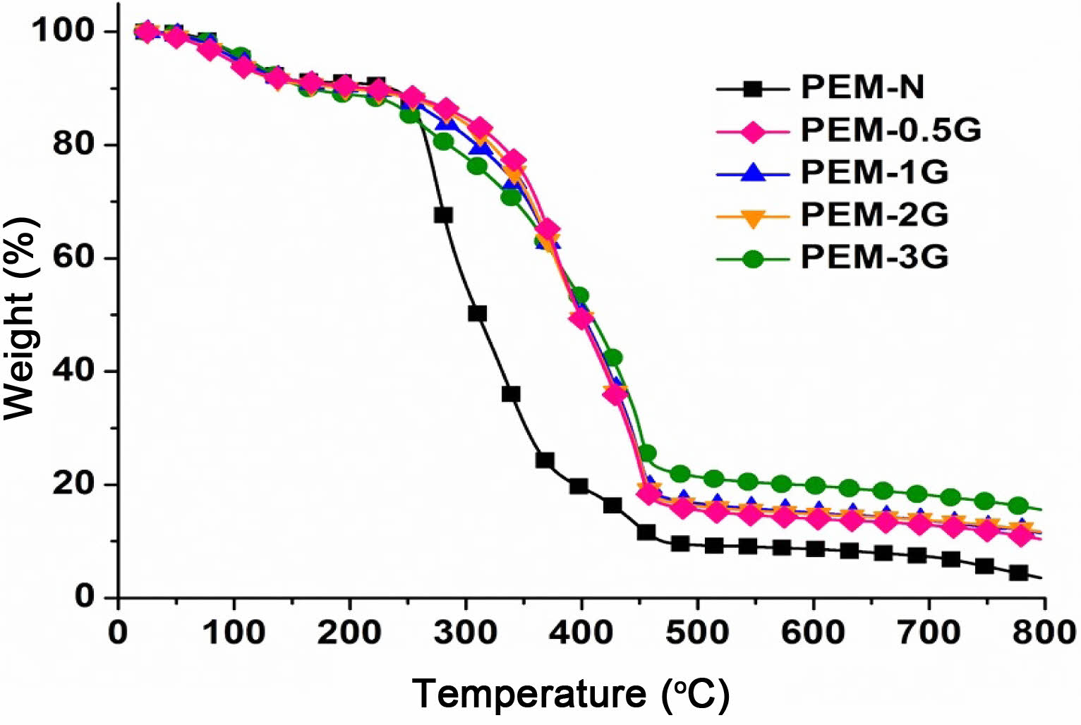
Thermal Stability of PEMs. TGA of PEM provides insight into susceptibility of the backbone chain and the pendent groups of the polymer when subjected to controlled heating program, and it gives information about weight changes i.e. weight loss of the polymer due to various thermochemical changes in polymers such as disintegration and oxidation, and physical processes including sublimation, evaporation, and desorption within the selected range of temperature at a selected heating rate. Neat and crosslinked membrane-samples that were subjected to TGA analysis in temperature span of 25 to 800 °C, at a heating rate of 10 °C/min, in an inert nitrogen atmosphere, the resultant thermograms is shown in Figure 6.
Overall, the thermograms revealed three prominent stages of weight loss in the temperature span of 25 to 150 °C, 150 to 300 °C, and 300 to 500 °C, which was due to dehydration, desulfonation and backbone chain degradation, respectively.8 Dehydration inherently involves the loss of free and hydrogen-bonded water molecules, that require less heat energy, and hence is usually observed at lower temperatures. Upon subsequently increasing the temperature from 150 to 300 °C, the sample absorbs more amount of heat energy that readily causes breakdown of the thermochemically labile functional groups and low-bond-energy pedant groups, which in the present case are -SO3H and unreacted -OH pendent groups. On the other hand, temperatures above 300 °C resulted in bond breakage of the polymer main chain by thermal degradation. As seen from the pattern of thermograms at the temperature span of 300-500 °C, the crosslinked PEMs were thermally more stable than the neat PEM, which can be attributed to the presence of acetal linkages in the crosslinked PEMs that requires high bond dissociation energy. As a result, they showed higher weight retention. In addition, the char residues of PEM-0.5G, PEM-1G and PEM-2G were found in the range of 10.9-15.60%, which is more than that of neat PEM-N (3.4%). Thus, it can be said that crosslinking of PVA-co-SSA by GA provided more thermal stability to the PEMs, which should be suitable for DMFCs operating at the temperature span of 60 to 80 °C.
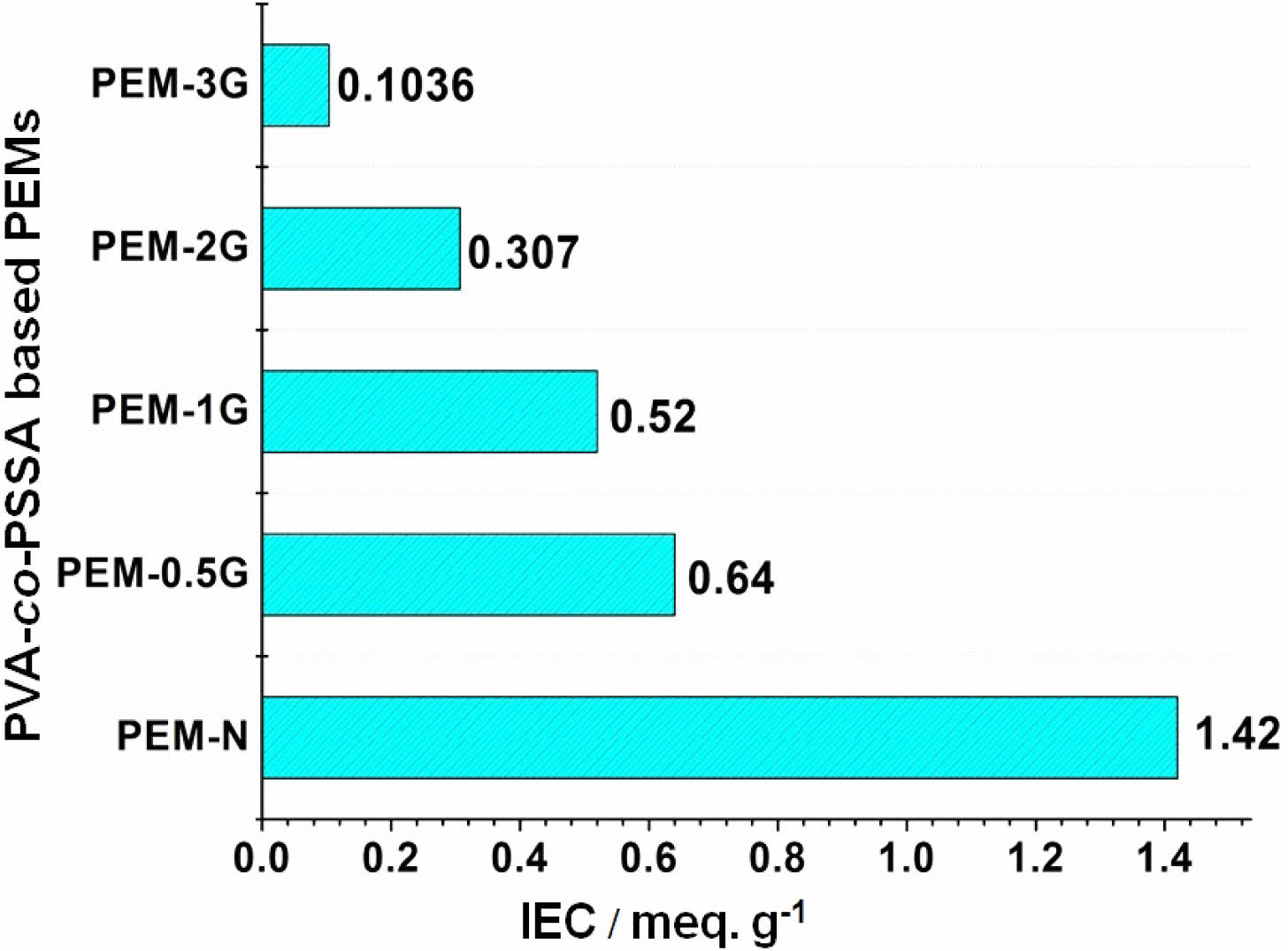
Ion-exchange Capacity and Proton Conductivity. PEMs based on PVA-co-SSA contain negatively charged ionic groups (-SO3H), which impart selective exchange and transport ability towards cationic groups, such as metal ions (Na+) and protons, respectively. Magnitude of ion-exchange and selective proton transport of PEMs can be determined by ion-exchange capacity (IEC) and proton conductivity, respectively. Figure 7 presents the measured IEC of crosslinked PEMs and uncrosslinked PEM-N, where the latter produced an IEC value of (1.42 meq./g) as compared to the value of (0.91 meq./g) exhibited by Nafion-117.52 It is seen that with increase in the GA concentration, the IEC of the membranes got reduced in the order 0.64 (PEM-0.5G) > 0.52 (PEM-1G) > 0.307 (PEM-2G) > 0.1036 (PEM-3G) meq./g. This declining trend in IEC with increasing GA content is expected because of diminution in the water uptake and swelling ratio of the PEMs with raise in GA concentration coupled with the formation of more dense rigid cellular structure that restricted accessibility of active sites for ion-exchange. Further, this reduction in IEC might be mostly related to the dramatic reduction in the concentration of -OH functionalities.
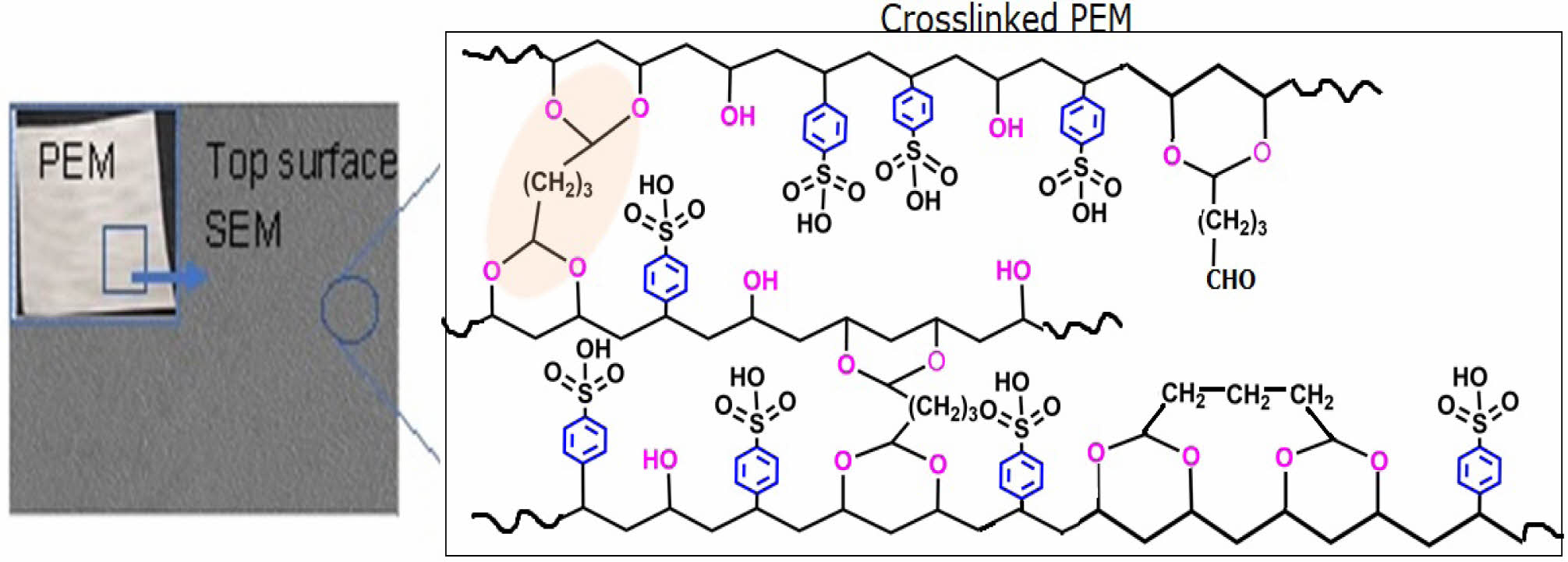
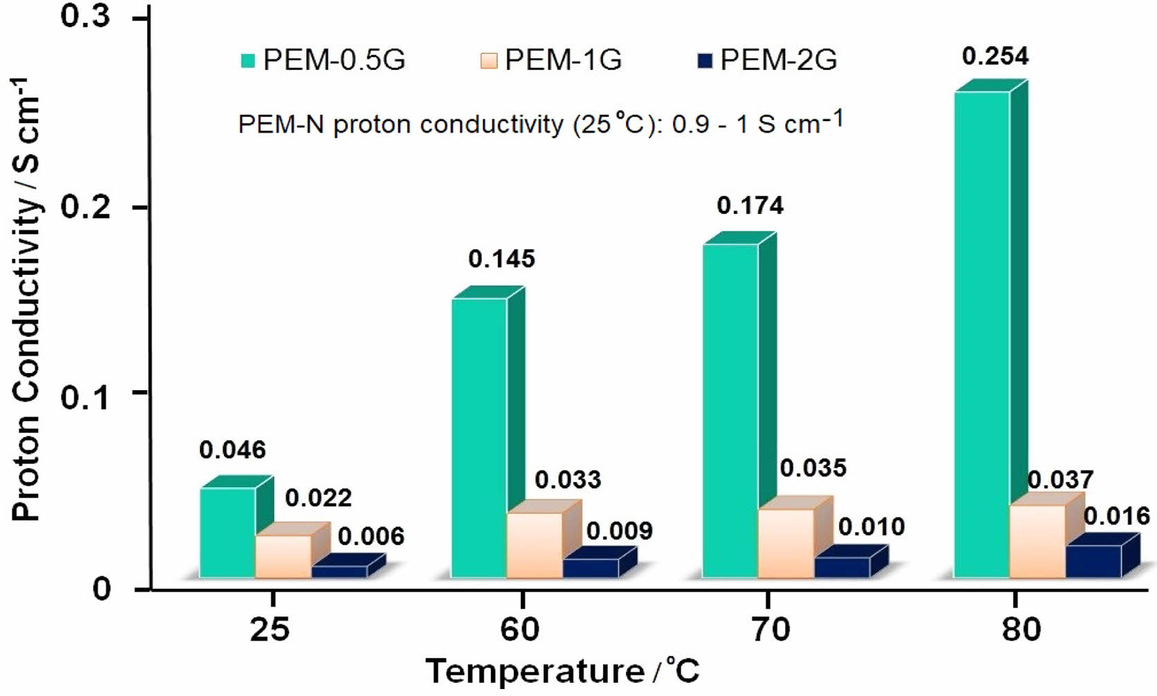
Similarly, proton conductivity of a PEM depends upon its water uptake and IEC, as well as the temperature at which the impedance measurement of the PEM is performed. Supporting information (Figure S2) shows the impedance spectra of the PEMs obtained at room temperature (25 oC), when the membrane-samples were scanned from 1 MHz to 1 Hz at 50 mV voltage amplitude. The proton conductivities of PEMs calculated according to eq. (5) has been presented in Figure 8 for measurements at the temperature regime of 25 to 80 oC. The neat PEM-N showed the lowest resistance of 250 Ω, while PEM-3G produced the highest resistance of 2350 Ω. Accordingly, the proton conductivity values obtained at 25 oC for PEM-N, PEM-0.5G, PEM-1G, PEM-2G and PEM-3G were in the order of 1.05 > 4.67×10⁻² > 2.15×10⁻² > 6.3×10⁻³ S/cm, respectively. The observed increment in the resistance was due to the formation of strong acetal linkages, which led to the reduction in hydration properties that plays a crucial role in the proton conduction via Grotthuss mechanism.23 Usually, increase in GA concentration results in higher crosslink density in PEM matrix that ultimately results in lowering of proton conductivity due to decrease in ion transport, water uptake and swelling ratio. Further, upon increasing the temperature at 100% RH, the ionic conductivity of PEM was found to increase for all the PEMs. For instance, PEM-0.5G exhibited values of proton conductivity of about 0.14 S/cm and 0.25 S/cm at 60 oC and 80 oC, respectively. Therefore, it can be said that increase in IEC, water uptake and temperature facilitated the proton conduction via the PEMs by both the Vehicular and Grotthuss mechanisms, as shown in Figure S3 (in supporting information). Herein, hydronium ion interacts with hydroxyl and sulfonate groups of polymer chain through hydrogen bonds and this proton swapping process within these functional groups results in proton transport i.e. by Grotthuss pathways, wherein, overall, proton moves to the water molecule combines with an adjacent ionic group. Beside that hydronium ion also interacts with water molecules present in pores i.e. channels as well as functional groups of polymers and proton transport takes place through electrochemical diffusion process i.e. by Vehicular mechanism.
Methanol Permeability and Selectivity. Methanol transport through the PEM from the anodic chamber to the cathodic chamber in a DMFC leads to generation of mixed potential at the cathode that results in lowering of the DMFC performance and cell polarization. Hence, PEMs should allow low MeOH permeability. Table 1 lists the measured MeOH permeability and selectivity values of the PVA-co-SSA based PEMs. It can be seen that PEM-0.5G showed MeOH permeability of (1.16×10⁻⁶ cm2/s), which is two times lower than Nafion-117 (2.89×10⁻⁶ cm2/s). This lower MeOH permeation was due to the presence of MeOH blocking sites, such as PVA units, in the PEMs. Further, as the crosslinking density increases, the MeOH crossover was found to decrease by almost tenfold for both PEM-1G and PEM-2G. Also, because of the high-water affinity groups presence in PVA and PSSA repeating units of PVA-co-SSA, the PEMs showed higher affinity towards water molecules than MeOH (because of the creation of strong intermolecular and intramolecular H-bonds). Besides, the PVA unit possesses a high affinity for water molecule than MeOH. Generally, a fully-hydrolyzed PVA excludes MeOH from the PEM matrix, and MeOH acts as a non-solvent for PVA. It must be noted in this regard that crossover of MeOH through PEMs takes place due to the combined effect of diffusion and ionic sites-facilitated MeOH transport through hydrogen bonding with hydronium ions. In addition, crosslinking resulted in contraction of the transport channels, leading to decrease in MeOH crossover.
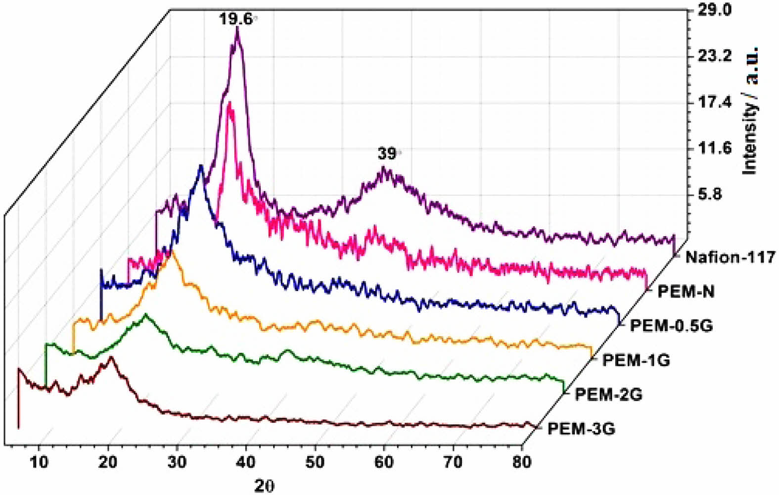
XRD Studies of PEMs. Measurement of XRDs of PEMs were performed in a 2θ range of 5-90oat room temperature (25 ºC), resulting XRD patterns as presented in Figure 9. Two diffraction peaks at 17o and 38o were observed for Nafion-117, clearly indicating some crystalline nature of this fluorinated membrane. For, neat and crosslinked PVA-co-SSA based PEMs, two diffraction peaks at 19.6o and 39o appeared, which indicates the presence of (100) and (101) crystal planes, respectively.50 This may be related to some ordered structure (partial crystallinity) due to H-bonding. However, the intensity and peak width were found to decrease with increase in the GA concentration; and finally, for PEM-3G, the intensity band at 40o disappeared. This signifies the diminution of the ordered structure and free volume within the PEM matrix due to increasing number of crosslink sites, i.e., acetal linkages.23,50 In fact, all the GA-crosslinked PEMs exhibited shifting of the (100) crystal plane towards a slightly lower diffraction angle, signifying the decreasing crystallinity of the PEMs with increasing GA content.
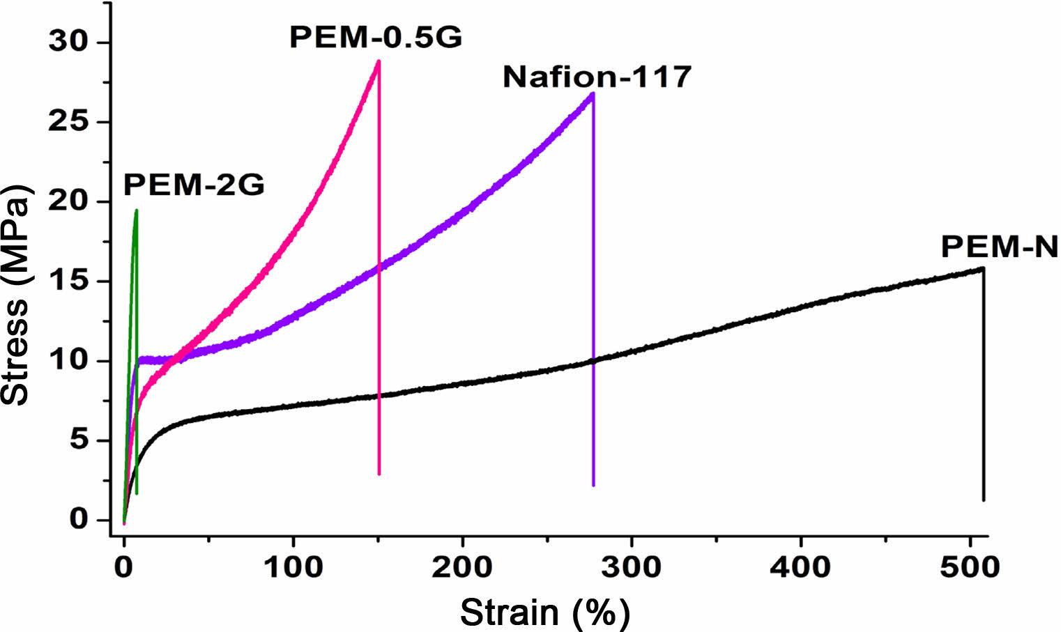
Tensile Properties. Evaluation of the mechanical strengths (tensile strengths) of the PEMs were conducted in a UTM, at a deformation rate of 10 mm/min, and the recorded stress-strain profile has been presented in Figure 10.The stress-strain curve indicates the pattern of deformation of the PEMs under applied load. It was difficult to find the yield point in case of the homogeneous PEMs. Nafion-117, PEM-N, PEM-0.5G, and PEM-2G showed tensile stress of 26.9, 16.0, 27.0, and 19.6 MPa respectively. The measured elongation (% strain) at the yield point was found to get decreased after the crosslinking of PEMs with GA, which is due to the formation of rigid crosslinks that restrict the deformation of polymer chains. However, the Young’s modulus, which denotes the ratio of stress/strain at a given load at the yield point, got enhanced due to the increase in the stiffness of the polymer chains. Moreover, the prominent brittle failure of PEM-2G, compared to PEM-0.5G, indicated better suitability of PEM-0.5G towards assembling in the FC stack under clamping pressure.
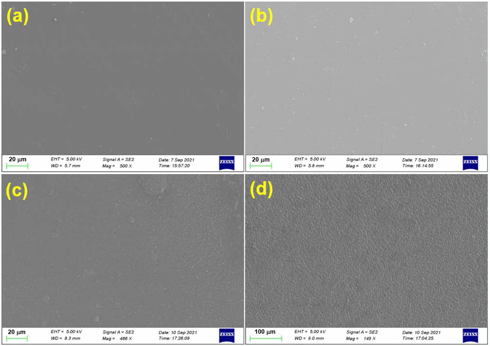
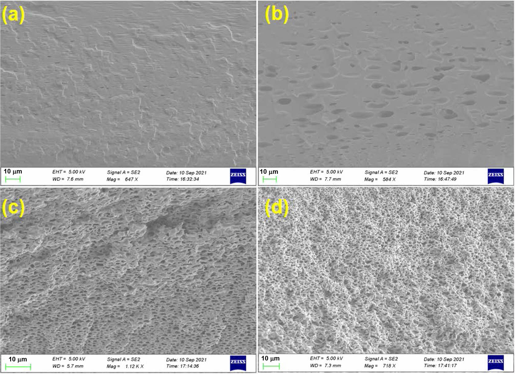
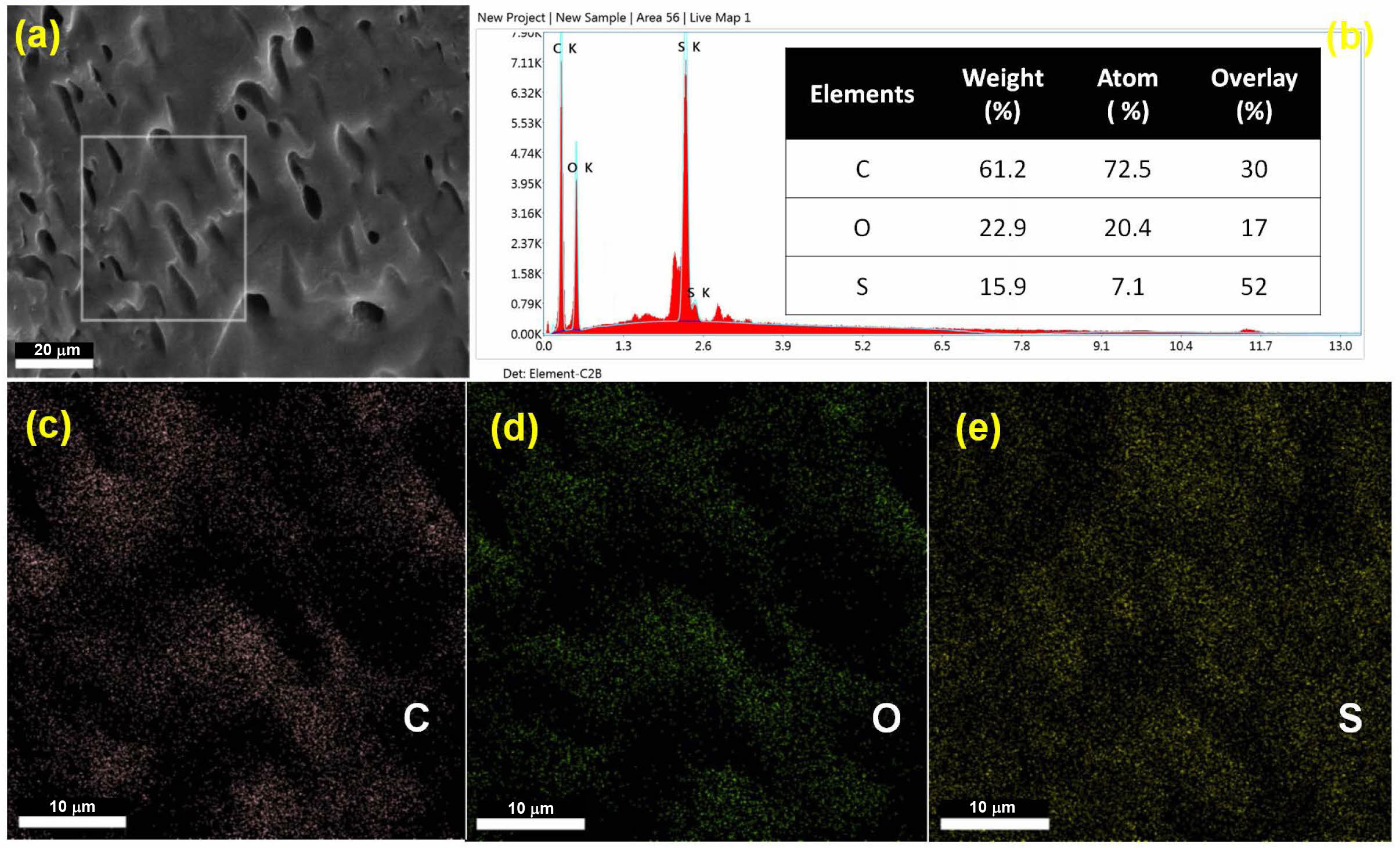
Surface Morphology Studies.The top-surface morphology of PEMs was evaluated using SEM, after coating with gold-platinum by sputtering. The surface topography and the cross-sectional images obtained for the PEMs are shown in Figure 11 and Figure 12, respectively. It was observed that both the neat and the crosslinked PEMs exhibited uniform dense surface topography. In addition, the presence of acetal linkages in crosslinked PEMs is prominently distinguishable in the cross-sectional views. It is believed that in the neat membranes, the polymers chains are closely packed together through intermolecular hydrogen bonding; thus, exhibiting a relatively denser morphology (Figure 12(a)). On the other hand, increasing crosslink density with increasing concentration of GA was responsible for creating a rigid-cell-type crosslinked network structure in the PEMs (Figure 12(b-d)). The increasing rigidity of the polymer chains with increasing GA concentration, and its effect on the PEMs’ morphology, is well in agreement with the observed tensile strengths of the PEMs. Further, to find the relative distribution of the constituent elements of the PEMs, PEM-0.5G sample was analyzed by the energy dispersive spectroscopy (EDX). The resulting elemental mapping of carbon (C), oxygen (O) and sulfur (S) element distribution within the selected surface area of the membrane is shown in Figure 13(a-b). The even distribution of carbon (C), oxygen (O) and sulfur (S) elements throughout the surface of the PEM can be observed from the elemental mapping (Figure 13(c-e)). Interestingly, the distribution of the “S” element was found to be more uniform, while the “O” element was dispersed in the cluster form. This may be due to acetalization between -OH groups of the PEM matrix and the GA molecules, which led to the formation of a rigid-cell-type structure.
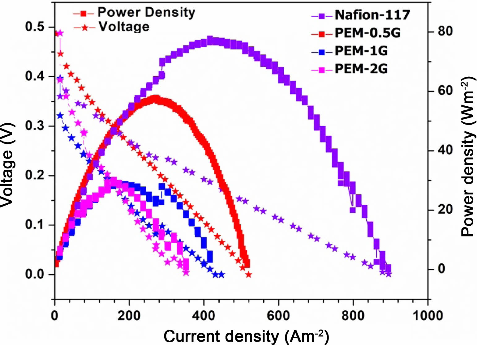
Single Cell Performance of DMFC. A total four numbers of MEAs were tested in DMFC cell, and designated as Nafion-117, PEM-0.5G, PEM-1G and PEM-2G. The neat PEM-N was dimensionally not stable due to excessive swelling, hence practically it was not possible to be tested in DMFC. The obtained current-voltage (I-V) curves for the Nafion-117 and the crosslinked PEMs (PEM-0.5G, PEM-1G and PEM-2G) are given in Figure 14.
The DMFC exhibited an open-circuit voltage (OCV) of around 0.6 V for Nafion-117, which produced the maximum current density value of 500 A/m2 at a peak power density of 79 W/m2 (when the FC was supplied with 2 M methanol and operated at 60 oC). Under similar conditions, PEM-0.5G showed a current density of 300 A/m2 at a peak power density of 59 W/m-2. As stated earlier, increasing the GA concentration give rise to reduction in the water absorption and the proton conductivity of the PVA-co-SSA based crosslinked PEMs, which subsequently resulted in lowering of the power density output of the FC. In this study, the I-V curves were obtained using a potentiostat that operated at varying current, and the resultant FC voltage was recorded automatically by a FC station. The observed decrease in the FC voltage with increasing draw current density can be attributed to the activation polarization losses, ohmic losses and concentration polarization losses.53 The activation losses are due to the requirement of voltage overpotential to overcome the activation energy of the oxidation-reduction reactions occurring at the membrane electrode interfaces. Ohmic loss is related to the electrical resistance of the various FC components, such membrane electrode assembly, electrodes, bipolar plate and gasket.53 Overall, rapid decrease in cell potential with increase in GA concentration used for PEMs crosslinking, may be attributed to increase in ohmic losses and mass transport limitation. Both of these losses have been merged, hence the slope of the drop (of voltage curve) is high. Although the performance of the copolymer-based MEA was low as compared to Nafion-117.
|
Figure 2 Schematic of PVA-co-SSA crosslinking/modification using GA through the formation acetal linkages. |
|
Figure 3 FTIR spectra of neat (PEM-N) and GA-crosslinked PEMs based on PVA-co-SSA. |
|
Figure 4 Water uptake of homogeneous PEMs crosslinked using different concentration of GA. |
|
Figure 5 Water contact angles of (a) PEM-N; (b) PEM-0.5G; (c) PEM-1G; (d) PEM-2G; (e) PEM-3G; (f) Nafion-117 |
|
Figure 6 TGA thermograms of neat (PEM-N), and cross-linked (PEM-0.5G, PEM-1G, PEM-2G and PEM-3G) membranes. |
|
Figure 7 Ion-exchange capacity of the neat (PEM-N), and GA cross-linked (PEM-0.5G, PEM-1G, PEM-2G and PEM-3G) membranes. |
|
Figure 8 Proton conductivity of PEM-N, PEM-0.5G, PEM-1G, and PEM-2G at different temperature conditions. |
|
Figure 9 XRD graphs for PEM-N, PEM-0.5G, PEM-1G, PEM-2G and PEM-3. |
|
Figure 10 Stress-strain graph for Nafion-117, PEM-N, PEM-0.5G, and PEM-2G. |
|
Figure 11 Surface topography of (a) PEM-N; (b) PEM-0.5G; (c) PEM-1G; (d) PEM-2G. |
|
Figure 12 FE-SEM images for cross-sectional view of (a) PEM-N; (b) PEM-0.5G; (c) PEM-1G; (d) PEM-2G. |
|
Figure 13 (a) FE-SEM images for cross-sectional view of PEM-0.5G; (b) EDX analysis; (c-e) elemental mapping of ‘C’, ‘O’, and ‘S’ for PEM-0.5G. |
|
Figure 14 I-V curve of DMFC assembled with PVA-co-SSA based PEMs. |
|
Table 1 Methanol permeability and selectivity of Nafion-117 and PVA-co-SSA based PEMs |
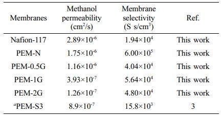
a block-type PEM based on PVA-b-PSSA polyelectrolyte crosslinked by GA |
In this study, homogeneous PEMs based on PVA-co-SSA have been successfully developed by solution casting technique. The properties of the un-crosslinked and the GA-crosslinked PEMs were analyzed to examine the effect of crosslink density on the various physicochemical and electrochemical characteristics of PEMs. Due to film forming ability of PVA-co-SSA, the PEMs obtained by GA-crosslinking was quite flexible. Crosslinking of membrane through acetal formation was confirmed by FTIR analysis. The PEM that was crosslinked using 0.5 M GA solution exhibited the most optimum values of swelling, water absorption, ionic conductivity and tensile strength. The proton conductivity of the optimized PEM-0.5G was determined to be 0.046 S/cm and 0.25 S/cm at 25 °C and 80 °C, respectively; while, the MeOH permeability of PEM-0.5G was found to be less than Nafion-117. The performance of a single cell DMFC, equipped with MEA that was based on PEM-0.5G, delivered a peak power density of 58 W/m2 at a current density of 300 A/m2.
- 1. Sajgure, M.; Kachare, B.; Gawhale, P.; Waghmare, S.; Jagadale, G. Direct Methanol Fuel Cell: A Review. Int. J. Curr. Eng. Technol. 2016, Special Issue 6, 8-11.
- 2. Gouda, M. H.; Konsowa, A. H.; Farag, H. A.; Elessawy, N. A.; Tamer, T. M.; Mohy Eldin, M. S. Novel Nanocomposite Membranes Based on Cross-linked Eco-friendly Polymers Doped with Sulfated Titania Nanotubes for Direct Methanol Fuel Cell Application. Nanomater. Nanotechnol. 2020, 10, 1-9.
-

- 3. Higa, M.; Feng, S.; Endo, N.; Kakihana, Y. Characteristics and Direct Methanol Fuel Cell Performance of Polymer Electrolyte Membranes Prepared from Poly(vinyl alcohol-b-styrene sulfonic acid). Electrochim. Acta. 2015, 153, 83-89.
-
- 4. Higa, M.; Mehdizadeh, S.; Feng, S.; Endo, N.; Kakihana, Y. Cell Performance of Direct Methanol Alkaline Fuel Cell (DMAFC) Using Anion Exchange Membranes Prepared from PVA-Based Block Copolymer. J. Membr. Sci. 2020, 597, 117618.
-
- 5. Park, M. S.; Choi, Y.; Lee, K. B.; Kim, J. H. Synthesis of PVA-g-POEM Graft Copolymers and Their Use in Highly Permeable Thin Film Composite Membranes. Chem. Eng. J. 2018, 346, 739-747.
-
- 6. Li, H.; Zhang, Y. M.; Xue, M. Z.; Liu, Y. G. Amphiphilic Block Copolymers of Polyvinyl Alcohol and Polystyrene and Their Surface Properties. Polym. J. 2005, 37, 841-846.
-
- 7. Mishra, A. K.; Choi, C.; Maiti, S.; Seo, Y.; Lee, K. S.; Kim, E.; Kim, J. K. Sequential Synthesis of Well-defined Poly(vinyl acetate)-block-polystyrene and Poly(vinyl alcohol)-block-poly- styrene Copolymers Using Difunctional Chloroamide-xanthate Iniferter. Polymer 2018, 139, 68-75.
-
- 8. Choudhury, R. R.; Gohil, J. M.; Mohanty, S.; Nayak, S. K. Synthesis and Characterization of Novel Functional Poly(vinyl alcohol-co-styrene sulfonic acid) Copolymers. Int. J. Polym. Anal. Charact. 2019, 24, 334-345.
-
- 9. Xie, W.; Tan, S.; Yang, J.; Luo, J.; Wang, C.; Wu, Y. Ionic Liquid Crystalline Composite Membranes Composed of Smectic Imidazolium Hydrogen Sulfate and Polyvinyl Alcohol for Anhydrous Proton Conduction. Ind. Eng. Chem. Res. 2020, 59, 8632-8639.
-
- 10. Molla, S.; Compan, V.; Gimenez, E.; Blazquez, A.; Urdanpilleta, I. Novel Ultrathin Composite Membranes of Nafion/PVA for PEMFCs. Int. J. Hydrog. Energy. 2011, 36, 9886-9895.
-
- 11. Yu, T. L.; Lin, H. L.; Shen, K. S.; Huang, L. N.; Chang, Y. C.; Jung, G. B.; Huang, J. C. Nafion/PTFE Composite Membranes for Fuel Cell Applications. J. Polym. Res. 2004, 11, 217-224.
-
- 12. Kim, J.; Yamasaki, K.; Ishimoto, H.; Takata, Y. Ultrathin Electrolyte Membranes with PFSA-vinylon Intermediate Layers for PEM Fuel Cells. Polymers (Basel). 2020, 12, 1730.
-
- 13. Kim, J. D.; Matsushita, S.; Tamura, K. Crosslinked Sulfonated Polyphenylsulfone-vinylon (CSPPSU-vinylon) Membranes for PEM Fuel Cells from SPPSU and Polyvinyl Alcohol (PVA). Polymers (Basel). 2020, 12, 1354.
-
- 14. Vani, R.; Ramaprabhu, S.; Haridoss, P. Mechanically Stable and Economically Viable Polyvinyl Alcohol-based Membranes with Sulfonated Carbon Nanotubes for Proton Exchange Membrane Fuel Cells. Sustain. Energy Fuels. 2020, 4, 1372-1382.
-
- 15. Salarizadeh, P.; Javanbakht, M.; Abdollahi, M.; Naji, L. Preparation, Characterization and Properties of Proton Exchange Nanocomposite Membranes Based on Poly(vinyl alcohol) and Poly(sulfonic acid)-grafted Silica Nanoparticles. Int. J. Hydrog. Energy. 2013, 38, 5473-5479.
-
- 16. Kamjornsupamitr, T.; Sangthumchai, T.; Youngmea, S.; Martwise, S. Proton Conducting Composite Membranes from Crosslinked Poly(vinyl alcohol) and Poly(styrene sulfonic acid)-functionalized Silica Nanoparticles. Int. J. Hydrog. Energy. 2018, 43, 11190-11201.
-
- 17. Beydaghi, H.; Javanbakht, M.; Badiei, A. Cross-linked Poly(vinyl alcohol)/sulfonated Nanoporous Silica Hybrid Membranes for Proton Exchange Membrane Fuel Cell. J. Nanostructure Chem. 2014, 4, 97.
-
- 18. Yagizatli, Y.; Ulas, B.; Cali, A.; Sahin, A.; Ar, I. Improved Fuel Cell Properties of Nano-TiO2 Doped Poly(vinylidene fluoride) and Phosphonated Poly(vinyl alcohol) Composite Blend Membranes for PEM Fuel Cells. Int. J. Hydrog. Energy. 2020, 45, 35130-35138.
-
- 19. Beydaghi, H.; Javanbakht, M.; Kowsari, E. Synthesis and Characterization of Poly(vinyl alcohol)/sulfonated Graphene Oxide Nanocomposite Membranes for Use in Proton Exchange Membrane Fuel Cells (PEMFCs). Ind. Eng. Chem. Res. 2014, 53, 16621-16632.
-
- 20. Gil-Castell, O.; Galindo-Alfaro, D.; Sánchez-Ballester, S.; Teruel-Juanes, R.; Badia, J. D.; Ribes-Greus, A. Crosslinked Sulfonated Poly(vinyl alcohol)/graphene Oxide Electrospun Nanofibers as Polyelectrolytes. Nanomaterials. 2019, 9, 397.
-
- 21. Abdullah, O. G.; Salman, Y. A.; Tahir, D. A.; Jamal, G. M.; Ahmed, H. T.; Mohamad, A. H.; Azawy, A. K. Effect of ZnO Nanoparticle Content on the Structural and Ionic Transport Parameters of Polyvinyl Alcohol Based Proton-conducting Polymer Electrolyte Membranes. Membranes. 2021, 11, 163.
-
- 22. Erkartal, M.; Usta, H.; Citir, M.; Sen, U. Proton Conducting Poly(vinyl alcohol) (PVA)/poly(2-acrylamido-2-methylpropane sulfonic acid) (PAMPS)/zeolitic Imidazolate Framework (ZIF) Ternary Composite Membrane. J. Membr. Sci. 2016, 499, 156-163.
-
- 23. Sahu, A. K.; Selvarani, G.; Pitchumani, S.; Sridhar, P.; Shukla, A. K.; Narayanan, N.; Banerjee, A.; Chandrakumar, N. PVA-PSSA Membrane with Interpenetrating Networks and Its Methanol Crossover Mitigating Effect in DMFCs. J. Electrochem. Soc. 2008, 155, B686.
-
- 24. DeLuca, N. W.; Elabd, Y. A. Direct Methanol Fuel Cell Performance of Nafion®/poly(vinyl alcohol) Blend Membranes. J. Power Sources. 2006, 163, 386-391.
-
- 25. Kasai, Y.; Okayama, T.; Guan, G.; Abudula, A. DMFC Performance of Cross-linked Sulfoethylcellulose/poly(vinyl alcohol) Blend Electrolyte Membranes. ECS Trans. 2012, 50, 2039-2047.
-
- 26. Choi, S.; Kim, J. R.; Cha, J.; Kim, Y.; Premier, G. C.; Kim, C. Enhanced Power Production of a Membrane Electrode Assembly Microbial Fuel Cell (MFC) Using a Cost Effective Poly[2,5-benzimidazole] (ABPBI) Impregnated Non-woven Fabric Filter. Bioresour. Technol. 2013, 128, 14-21.
-
- 27. Grandi, S.; Mustarelli, P.; Carollo, A.; Tomasi, C.; Quartarone, E.; Magistris, A. PWA Doped SiO2 Peg Hybrid Materials of Class II. Mater. Sci. Appl. 2010, 1, 285-291.
-
- 28. Thakur, V. K.; Vennerberg, D.; Kessler, M. R. Green Aqueous Surface Modification of Polypropylene for Novel Polymer Nanocomposites. ACS Appl. Mater. Interfaces. 2014, 6, 9349-9356.
-
- 29. Gohil, J. M.; Karamanev, D. G. Novel Pore-filled Polyelectrolyte Composite Membranes for Cathodic Microbial Fuel Cell Application. J. Power Sources. 2013, 243, 603-610.
-
- 30. Kim, D. H.; Park, J. S.; Choun, M.; Lee, J.; Kang, M. S. Pore-filled Anion-exchange Membranes for Electrochemical Energy Conversion Applications. Electrochim. Acta. 2016, 222, 212-220.
-
- 31. Song, H. B.; Park, J. H.; Park, J. S.; Kang, M. S. Pore-filled Proton-exchange Membranes with Fluorinated Moiety for Fuel Cell Application. Energies. 2021, 14, 4433.
-
- 32. Wu, C. S.; Lin, F. Y.; Chen, C. Y.; Chu, P. P. A Polyvinyl Alcohol/p-sulfonate Phenolic Resin Composite Proton Conducting Membrane. J. Power Sources. 2006, 160, 1204-1210.
-
- 33. Blanco, J. F.; Nguyen, Q. T.; Schaetzel, P. Novel Hydrophilic Membrane Materials: Sulfonated Polyethersulfone Cardo. J. Membr. Sci. 2001, 186, 267-279.
-
- 34. Park, H. B.; Nam, S. Y.; Rhim, J. W.; Lee, J. M.; Kim, S. E.; Kim, J. R.; Lee, M. Y. Gas‐transport Properties Through Cation‐exchanged Sulfonated Polysulfone Membranes. J. Appl. Polym. Sci. 2002, 86, 2611-2617.
-
- 35. Choudhury, R. R.; Gohil, J. M.; Dutta, K. Poly(vinyl alcohol)-Based Membranes for Fuel Cell and Water Treatment Applications: A Review on Recent Advancements. Polym. Adv. Technol. 2021, 32, 1042-7147.
-
- 36. Lewandowski, A.; Skorupska, K.; Malinska, J. Novel Poly(vinyl alcohol)-KOH-H2O Alkaline Polymer Electrolyte. Solid State Ion. 2000, 133, 265-271.
-
- 37. Vargas, R. A.; Zapata, V. H.; Matallana, E.; Vargas, M. A. More Thermal Studies on the PVOH/H3PO2/H2O Solid Proton Conductor Gels. Electrochim. Acta. 2001, 46, 1699-1702.
-
- 38. Rhim, J. W.; Hwang, H. S.; Kim, D. S.; Park, H. B.; Lee, C. H.; Lee, Y. M.; Moon, G. Y.; Nam, S. Y. Aging Effect of Poly(vinyl alcohol) Membranes Crosslinked with Poly(acrylic acid-co-maleic acid). Macromol. Res. 2005, 13, 135-140.
-
- 39. Kang, M. S.; Kim, J. H.; Won, J.; Moon, S. H.; Kang, Y. S. Highly Charged Proton Exchange Membranes Prepared by Using Water Soluble Polymer Blends for Fuel Cells. J. Membr. Sci. 2005, 247, 127-135.
-
- 40. Qiao, J.; Hamaya, T.; Okada, T. New Highly Proton Conductive Polymer Membranes Poly(vinyl alcohol)-2-acrylamido-2-methyl-1-propanesulfonic acid (PVA-PAMPS). J. Mater. Chem. 2005, 15, 4414-4423.
-
- 41. Higa, M.; Sugita, M.; Maesowa, S. I.; Endo, N. Poly(vinyl alcohol)-based Polymer Electrolyte Membranes for Direct Methanol Fuel Cells. Electrochim. Acta. 2010, 55, 1445-1449.
-
- 42. Vinothkannan, M.; Kim, A. R.; Yoo, D. J. Sulfonated Graphene Oxide/Nafion Composite Membranes for High Temperature and Low Humidity Proton Exchange Membrane Fuel Cells. RSC Adv. 2018, 8, 7494-7508.
-
- 43. Higa, M.; Mehdizadeh, S.; Feng, S.; Endo, N.; Kakihana, Y. Cell Performance of Direct Methanol Alkaline Fuel Cell (DMAFC) Using Anion Exchange Membranes Prepared from PVA-based Block Copolymer. J. Membr. Sci. 2020, 597, 117618.
-
- 44. Sahu, A. K.; Selvarani, G.; Bhat, S. D.; Pitchumani, S.; Sridhar, P.; Shukla, A. K.; Narayanan, N.; Banerjee, A.; Chandrakumar, N. Effect of Varying Poly(styrene sulfonic acid) Content in Poly(vinyl alcohol)-poly(styrene sulfonic acid) Blend Membrane and Its Ramification in Hydrogen-oxygen Polymer Electrolyte Fuel Cells. J. Membr. Sci. 2008, 319, 298-305.
-
- 45. Higa, M.; Feng, S.; Endo, N.; Kakihana, Y. Characteristics and Direct Methanol Fuel Cell Performance of Polymer Electrolyte Membranes Prepared from Poly(vinyl alcohol-b-styrene sulfonic acid). Electrochim. Acta. 2015, 153, 83-89.
-
- 46. Attaran, A. M.; Javanbakht, M.; Hooshyari, K.; Enhessari, M. New Proton Conducting Nanocomposite Membranes Based on Poly Vinyl Alcohol/Poly Vinyl Pyrrolidone/BaZrO3 for Proton Exchange Membrane Fuel Cells. Solid State Ion. 2015, 269, 98-105.
-
- 47. Kumar, P.; Bharti, R. P.; Kumar, V.; Kundu, P. P. Polymer Electrolyte Membranes for Microbial Fuel Cells: Part A. Nafion-based Membranes. In Progress and Recent Trends in Microbial Fuel Cells; Kundu, P. P., Dutta, K., Eds.; Elsevier: Cambridge, 2018; pp 47-72.
-
- 48. Colpan, C. O.; Nalbant, Y.; Ercelik, M. Fundamentals of Fuel Cell Technologies. In Comprehensive Energy Systems;Dincer, I., Ed.; Elsevier: Cambridge, 2018; pp 1107-1130.
-
- 49. Kim, D.; Park, H. B.; Rhim, J. W.; Lee, Y. M. Preparation and Characterization of Crosslinked PVA/SiO2 Hybrid Membranes Containing Sulfonic Acid Groups for Direct Methanol Fuel Cell Applications. J. Membr. Sci. 2004, 240, 37-48.
-
- 50. Rudra, R.; Kumar, V.; Kundu, P. P. Acid Catalysed Cross-linking of Poly Vinyl Alcohol (PVA) by Glutaraldehyde: Effect of Crosslink Density on the Characteristics of PVA Membranes Used in Single Chambered Microbial Fuel Cells. RSC Adv. 2015, 5, 83436-83447.
-
- 51. Richard, P. W. Properties of Triglyceride-based Thermosets. In Bio-Based Polymers and Composites; Richard, P. W., Sun, X. S., Eds.; Academic Press, 2005; pp 202-225.
-
- 52. Li, G.; Zhao, C.; Li, X.; Qi, D.; Liu, C.; Bu, F.; Na, H. Novel Side-chain-type Sulfonated Diphenyl-based Poly(arylene ether sulfone)s with a Hydrogen-bonded Network as Proton Exchange Membranes. Polym. Chem. 2015, 6, 5911-5920.
-
- 53. Ohayre, R.; Cha, S. W.; Colella, W.; Prinz, F. B. Fuel Cell Characterization. In Fuel Cell Fundamentals; Ohayre, R., Cha, S. W., Colella, W., Prinz, F. B., Eds.; John Wiley & Sons: New York, 2016; pp 237-270.
-
- Polymer(Korea) 폴리머
- Frequency : Bimonthly(odd)
ISSN 0379-153X(Print)
ISSN 2234-8077(Online)
Abbr. Polym. Korea - 2022 Impact Factor : 0.4
- Indexed in SCIE
 This Article
-
2022; 46(5): 627-639
Published online Sep 25, 2022
- 10.7317/pk.2022.46.5.627
- Received on May 8, 2022
- Revised on Jun 17, 2022
- Accepted on Jun 21, 2022
Services
- Full Text PDF
- Abstract
- ToC
- Acknowledgements
- Conflict of Interest
- Supporting Information
Introduction
Experimental
Results and Discussion
Conclusions
- References
Shared
Correspondence to
- M. Gohil
-
*Advanced Polymer Design and Development Research Laboratory (APDDRL), School for Advanced Research in Petrochemicals (SARP), Central Institute of Petrochemicals Engineering & Technology (CIPET), Bengaluru-562149, Karnataka, India
**Advanced Research School for Technology and Product Simulation (ARSTPS), School for Advanced Research in Petrochemicals (SARP), Central Institute of Petrochemicals Engineering and Technology (CIPET), Chennai-600032, Tamil Nadu, India - E-mail: jay21480@yahoo.co.in
- ORCID:
0000-0002-1262-6858
Hyecheon Building(Room 601), #354, Gangnam-Daero, Gangnam-Gu, Seoul 06242, Korea
TEL : 82-2-568-3860, 561-5203, 569-3860 FAX : 82-2553-6938 E-mail: polymer@polymer.or.kr