


- Enhanced Electrochemical Properties of Electron Beam Irradiated Carbon Nanofibers as an Electrode for Supercapacitor
Minjae Kim and Sang Eun Shim*,†

School of Mechanical and Control Engineering, Handong Global University, 558 Handong- ro, Buk-gu, Pohang, Gyeongbuk 37554, Korea
*Department of Chemical Engineering, Inha University, 100 Inha-ro, Michuhol-gu, Incheon 22212, Korea- 전자빔이조사된탄소나노섬유슈퍼커패시터전극전기화학적성능개선
김민재 ·심상은*,†
한동대학교 기계제어공학부, *인하대학교 화학공학과
Reproduction, stored in a retrieval system, or transmitted in any form of any part of this publication is permitted only by written permission from the Polymer Society of Korea.
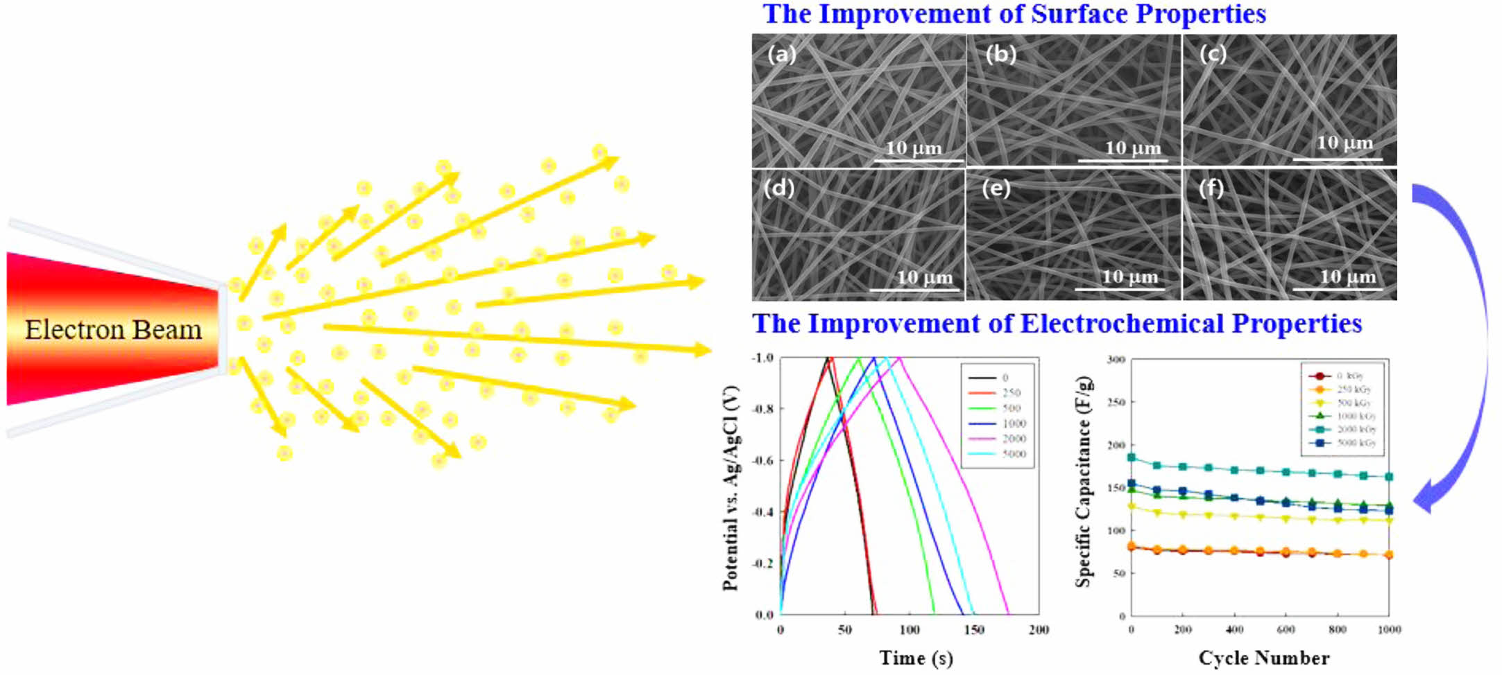
Surface properties of carbon nanofibers (CNFs) were modified by electron beam (e-beam) irradiation, and electrochemical performances of treated CNFs as the supercapacitor electrode were investigated. Since the capacity of a supercapacitor is affected by the surface properties of the electrode, the improvement of the electrode surface properties using various techniques has been widely investigated, however, e-beam treatment on CNFs is quite limited. In this study, CNFs were manufactured through the carbonization process of polymer nanofibers fabricated using electrospinning, and structural and electrochemical properties of e-beam irradiated CNF electrodes were analyzed. By the e-beam treatment, the diameter of CNF decreased from 646 nm to 457 nm, and the surface area increased from 529 m2g-1 to 1452 m2g-1. e-Beam irradiated CNFs were used as supercapacitor electrodes to analyze their electrochemical performance and showed a great electrochemical performance compared to the pristine CNFs.
본 연구에서는 탄소나노섬유의 표면 특성을 전자 빔 조사를 통하여 개선하였고, 슈퍼커패시터 전극으로 활용하여 개선된 전기화학적 성능을 확인하였다. 슈퍼커패시터의 용량은 전극의 표면 성능과 밀접한 관계가 있기 때문에, 다양한 기법을 활용한 전극 표면 개선 연구가 진행되고 있으나, 전자 빔을 사용하여 탄소섬유의 표면을 개선한 전극 연구는 미비한 실정이다. 본 연구에서는 전기 방사 기법을 활용하여 제조된 고분자 나노 섬유를 탄화 과정을 거쳐 탄소나노섬유로 제조하고, 전자 빔을 조사하여 탄소나노섬유의 구조적, 전기화학적 성능을 분석하였다. 전자 빔을 조사한 탄소나노섬유의 직경은 646 nm에서 457 nm까지 감소하였으며, 이에 따른 표면적이 529 m2g-1부터 1452 m2g-1까지 증가하였다. 전자 빔이 조사된 탄소나노섬유는 슈퍼커패시터 전극으로 활용되어 전기화학 성능을 분석하였고, 전자 빔이 처리되지 않은 탄소나노섬유는 전극 용량 대비 개선된 표면특성으로 인하여 우수한 전기화학적 성능을 보였다.
E-beam irradiation process was used for the enhancement of electrochemical and surface properties of carbon nanofibers (CNFs). E-beam treatment with various intensities affected the increase in the surface area of CNFs from 529 to 1452 m2 g-1, which provided a decisive reason for the improved electrochemical properties of CNF electrode; capacitance increased from 74.8 to 177.6 F g-1.
Keywords: carbon nanofiber, electron beam, supercapacitor, electrospinning.
This work was supported by Inha University Research Grant.
The authors declare that there is no conflict of interest.
Supercapacitor has been intensively investigated as an energy storage device with high power density, charge/discharge cycle life, and energy efficiency.1 There are two different types of supercapacitors: electrical double-layer capacitors (EDLCs) and pseudo capacitor. The formation of a double layer on the surface of electrode materials is a major cause of charge storage in EDLC. However, in a pseudo-capacitor, the charge is stored on both the Faradaic redox reaction and the electrical double layer on the electrode surface. Therefore, pseudo-capacitors usually have larger charges than EDLC counterparts.2 Among the various materials used for supercapacitor electrode, carbon nanofibers (CNFs), derived from polymer such as polyacrylonitrile (PAN) or polymethylmethacrylate (PMMA), has a great potential because of the tremendous surface area and high electrical properties to be adjusted to supercapacitor electrode.3-5 CNFs are majorly produced by processing PAN precursor nanofiber because of its relatively high carbon yield.6 After the electrospinning process, PAN fiber undergoes two-step thermal treating, stabilization and carbonization to turn into CNFs.7
Since electrospinning has patented in 1934, electrospun fibers featuring various robust properties have already applicated remarkable use in areas such as cell scaffolds, sensors, enzyme carriers in drug delivery system, and filter membranes.8-12 Above all, it has been widely used to produce CNFs because electrospinning makes the diameter of nanofiber controllable. Therefore, CNFs produced by electrospinning have a large surface area attributed from web-like nanostructure, high electrical and thermal conductivity and remarkably small and adjustable pore size which are representative properties for supercapacitor electrodes.13
Electrospinning produces ultrafine polymer fibers featuring micro and nano diameters. This property is acquired by utilizing an electrostatic field applied between a polymer mixture and the surface of metal collector to induce self-assembly of nanoscale fibers which have tempted remarkable interest by advantage of their unique flexibility, durability, and exceptional surface properties to volume ratio characteristics that bulk materials do not possess.14
Electrochemical and physical characterizations of PAN-based CNFs have been widely studied. Also, there are numerous methods to improve its electrochemical properties such as composite with metal oxide, conductive polymer or other carbon materials and activation by applying thermal energy. However, to the best of the author’s knowledge, the use of e-beam energy on CNFs has not been attempted. The main advantages of electron beam (e-beam) irradiation are (i) the intensity or dose of e-beam can be easily controlled by set voltage, current or time, (ii) e-beam can apply adequate energy to substrate to induce desirable reaction in relatively short time and (iii) the desired reaction can occur inside and outside of substrate simultaneously since e-beam can penetrate samples by regulating electrical voltage.15 Because of these attractive properties, e-beam has received significant attention as a versatile energy source and has been used in various fields such as crosslinking, degradation, grafting, functionalization, stiffening, and sterilization.16-21
In this work, we demonstrate and identify the potentiality and effect of e-beam irradiation on PAN-based carbon nanofiber mats, especially focusing on their novel electrode performance for supercapacitors. We prepared PAN nanofibers by electrospinning, and they were all carbonized at the same thermal and atmospheric conditions. As-prepared CNF mats were irradiated by e-beam with specific voltage and current in air condition. The e-beam dose was varied from 0 to 5000 kGy to determine the most optimum dose level to improve electrochemical properties of CNFs. The charge storage properties of the CNFs were characterized by electrochemical analysis.
Materials. Polyacrylonitrile (PAN, Mw: 150000 g/mol) for base material of carbon nanofiber was supplied by Sigma-Aldrich (Germany). As the solvent, N,N-dimethylformamide (DMF, assay 99.0% min.) was purchased from OCI Company Ltd. (South Korea).
Electrospinning of PAN Nanofiber Sheet. PAN nanofiber sheets were prepared by using electrospinning. PAN was dissolved into DMF with 12 wt.% concentration for uniform and ultrafine fibers. In order to fabricate a homogenous mixture, PAN was directly added to 65 ℃ DMF solvent and the solution was stirred for 8 hrs. After mixing, the solution was loaded into a syringe which was mounted on a syringe pump and fed through the capillary nozzle. The solution fed at the rate of 1.0 mL min-1 and 18 kV of voltage was applied to form an electrical field in the gap between the cylindrical collector covered with aluminum foil and capillary nozzle where the solution flows out. During the electrospinning, the cylindrical collector located 20 cm ahead to the nozzle rotated at 300 rpm speed. All the electrospinning conditions such as voltage, feed rate, rotation speed of collector and the concentration of PAN solution were fixed identically to acquire bead-free and fine PAN nanofibers. After 2 hrs of electrospinning for suitable thickness, collected PAN nanofiber sheets were dried under vacuum over 24 hrs.
Preparation of CNFs by Thermal Treating. As-prepared PAN nanofiber sheets were placed into a furnace for thermal treatment. They went through stabilization and carbonization processes by changing thermal and atmospheric conditions. Starting from the temperature up to 280 ℃, the stabilization of PAN occurred for 2 hrs in the oxygen condition. Through this process, the structure of PAN changes into cyclic shape and becomes more stable. The carbonization process follows the stabilization process by heating temperature until it reaches 900 ℃, where stabilized PAN nanofiber turned into carbon nanofiber by allowing 2 hrs in Ar atmosphere. After cooling down in the same atmospheric condition of carbonization, resultant CNFs were obtained.
E-beam Irradiation of Carbon Nanofibers. The low-energy electron accelerator managed by Korea Atomic Energy Research Institute (KAERI) was used for e-beam irradiation on as-prepared CNFs. The acceleration potential was kept constant at 0.2 MeV with a beam irradiating current of 0.5 mA. CNF mats were placed on a metal plate located perpendicularly to the direction of e-beam and each sample was irradiated in different time to reach the intended dose ranging of 0, 250, 500, 1000, 2000, or 5000 kGy, controlled six different irradiated samples, under atmospheric conditions.
Characterization. The diameter of the electrospun fibers was examined by scanning electron microscopy (SEM, HITACHI, S-4300, Japan). Prior to analysis, all samples were sputter-coated with platinum. The Brunauer-Emmett-Teller (BET, ASAP 2020, Micromeritics Inc., USA) analysis in nitrogen gas condition was used to evaluate the surface area and pore volume of the CNFs. X-ray photoelectron spectroscopy (XPS, Thermo scientific, K-Alpha, Thermo Scientific, USA) and fourier transform infrared spectrophotometry (FTIR, VERTEX 80V, Bruker, USA) were conducted on CNFs to analyze the variation of functional groups of CNFs before and after irradiation in the 4000-600 cm-1 range. Thermogravimetric analysis (TGA, TG209F3, Netzsch, Germany) was implemented with a heating rate of 10 °C min-1 from 100 to 800 °C under an Ar atmosphere to investigate the thermal stability of the e-beam irradiated CNFs. An X-ray diffractometer (XRD, Rigaku, DMAX-2500, Rigaku, Japan) with Cu-Kα radiation (λ = 1.5450 Å) was used to measure the crystallinity of nanofibers. Raman spectra were obtained on Brucker RFS 100/S (Brucker, USA) with the excitation wavelength of 1064 nm from an Nd/YAG laser power of 25 mW. Prior to measuring the electrochemical properties of CNFs, three-electrode cells were built in 6 M KOH electrolyte solution with a platinum wire as a counter electrode and Ag/AgCl as a reference electrode. Electrochemical tests were performed with a potentiostat (Bio-Logic, France). In order to obtain the electrochemical specific capacitance of electrodes, cyclic voltammetric curve (CV) analysis was conducted at a scan rate of 10 mV/s. Galvanostatic constant current charge-discharge tests were carried out at 1 A g-1 in the applied potential window range between -1 V to 0 V.
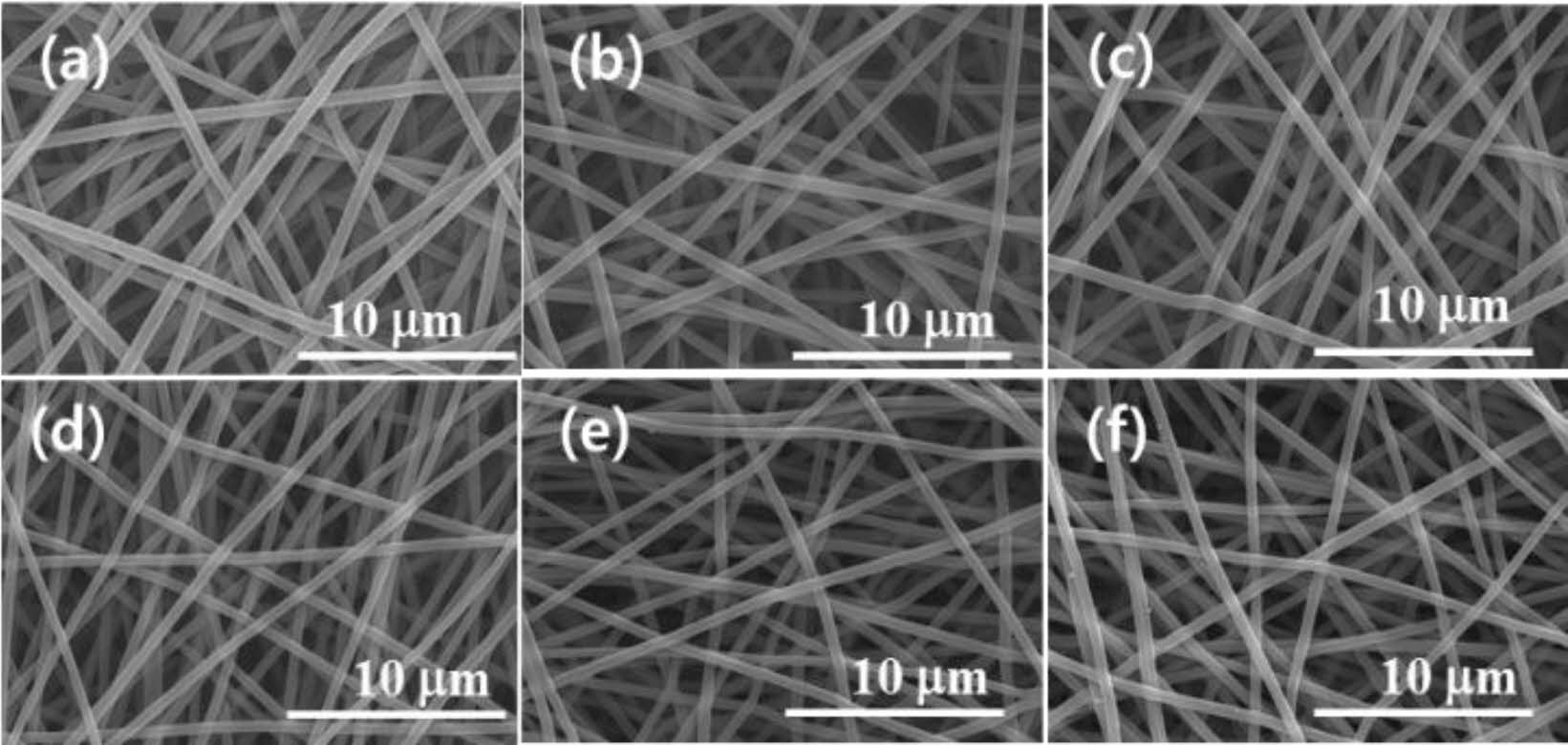
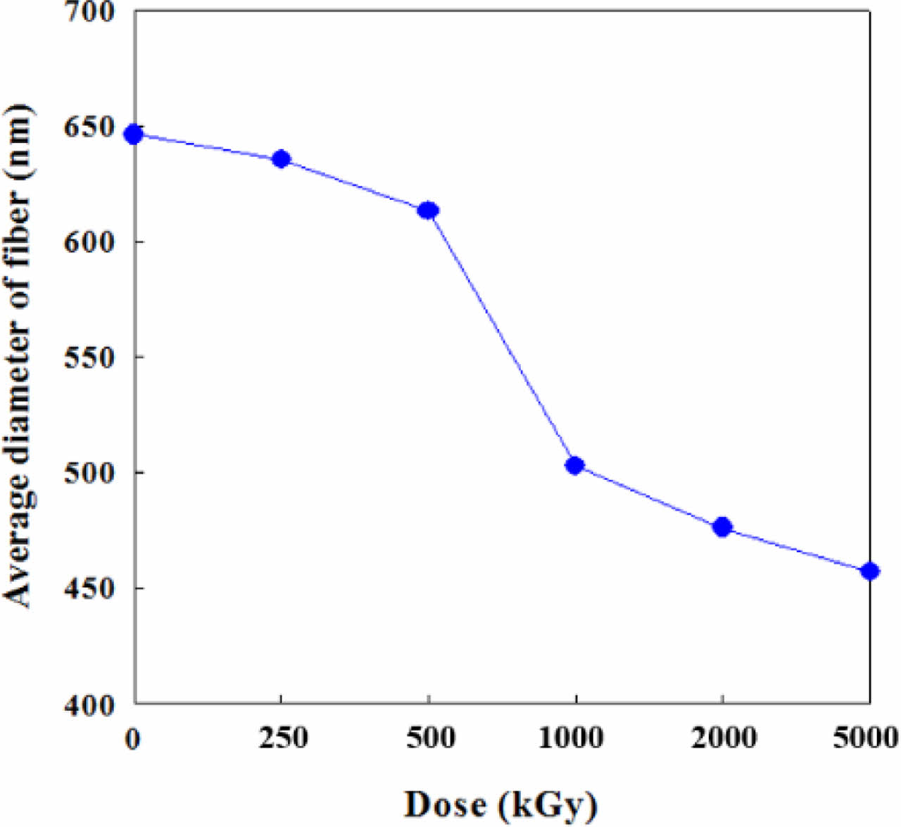
Morphology and Surface Properties. Figure 1 shows the effect of e-beam treatment on the CNF. The straight and long CNFs were stacked up randomly to form a web-like shape. This phenomenon is explained that e-beam treatment of a polymer fiber causes the shrinkage of fiber which makes the diameter reduce. The high irradiation energy caused by e-beam treatment leads to the change of physical properties of various materials through main-chain scission and cross-linking.22 In the SEM microphotographs, the average diameter of pristine CNFs was 646 nm. Starting from this value, the diameter of CNFs had been decreased gradually until it reached 457 nm with the increase in irradiation intensity from 250 to 5000 kGy as shown in Figure 2.
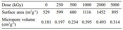
BET results summarized in Table 1 can be explained in connection with the shrinkage of diameter originated from e-beam irradiation. Due to the decrease of diameter, the surface area of CNF increased dramatically from 529 to 1452 m2 g-1 until the irradiation dose reached to 2000 kGy. As the dose rose up to 5000 kGy, the surface area decreased to 895 m2 g-1. This result seems to be related to random morphology change using e-beam by repeatedly destroying and crosslinking the bond of each unit. Therefore, optimized range of irradiation condition is required for the maximization of surface area of CNFs.
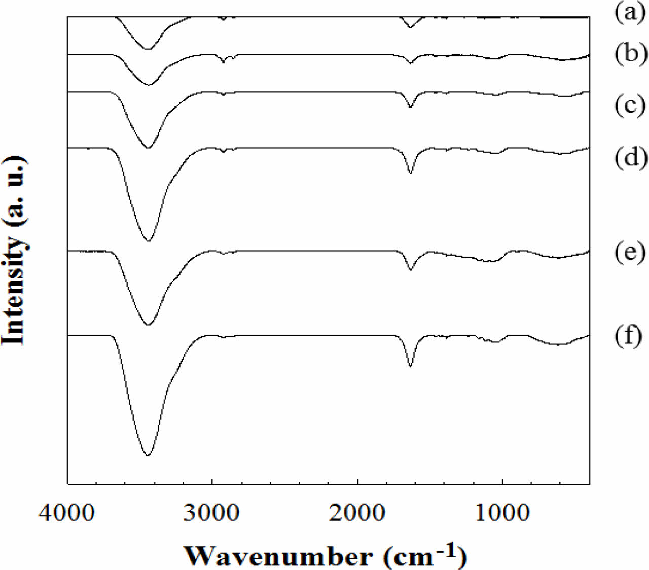
FTIR and XPS Results of e-beam Irradiated CNFs. FTIR spectra in Figure 3 show the change of chemical bond in CNFs according to the e-beam irradiation intensity. In the FTIR results of CNFs, the characteristic FTIR spectra of irradiated CNF are almost similar to that of the non-irradiated one. Nevertheless, several different bands are observed at 3600-3000, 2921, and 1635 cm-1. The broad peak region between 3600 and 3000 cm-1 is owing to the N-H bond on CNF which makes the CNFs have more hydrophilic property.23 The small peaks near 2921 cm-1 are sp3 hydrocarbon peaks created from the destroyed C=C or C-C bonds in non-irradiated CNF.24 The peak at 1635 cm-1 represents C=N bond from non-irradiated CNF and the peak intensity became weaker compared to the intensity of other peaks because C=N bonds were converted to C-H or N-H peaks due to the energy irradiated from e-beam.25
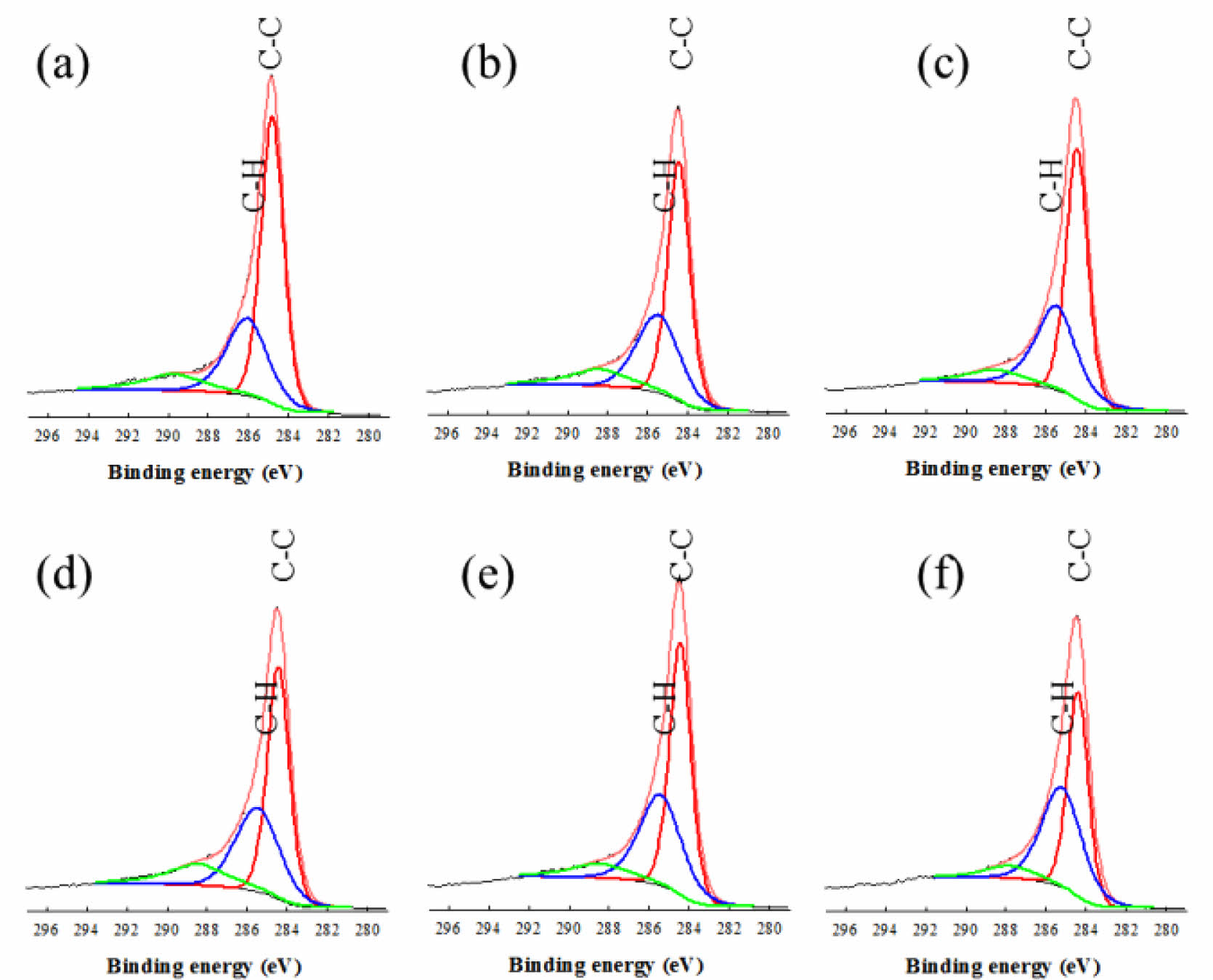
XPS further confirmed the transition of bonds during e-beam irradiation, as shown in Figure 4. The C1s core level of CNFs can be deconvoluted into three Gaussian curves at 284.64, 285.98, and 289.87 eV which indicate C-C, C-H/C-N and C=O bonding, respectively.26,27 As the dose level increased from 0 to 2000 kGy, C-H peak becomes greater compared to the C-C peak. Being irradiated by e-beam, the C-C bonds in the cyclic structure of CNF were destroyed and re-ordered to the C-H bonds.
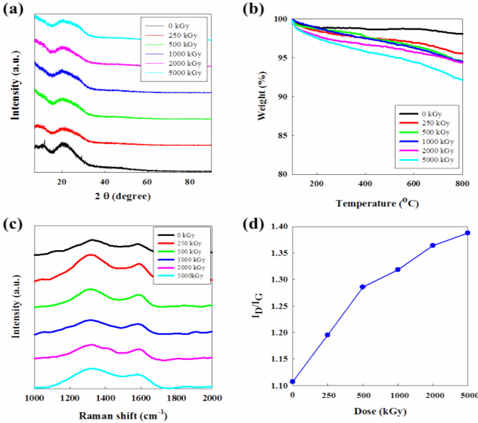
XRD, TGA, and Raman Results of CNFs. In Figure 5(a), XRD spectra of irradiated CNFs show that the e-beam irradiation process damages the structure of CNFs compared to non-irradiated fibers. All XRD results show one clear peak at around 23o which is a typical peak shown in the structure of carbon materials. At dose range from 250 to 5000 kGy, however, it is difficult to found out the obvious difference in the intensity of irradiation. It means the e-beam irradiation might affect the crystallinity of carbon structure, but the change of crystallinity by the intensity of e-beam does not have a continuous tendency. Nevertheless, we confirmed the improvement of surface properties detailed in the increase of surface area and hydrophilicity for the electrochemical reaction in an aqueous supercapacitor system.
TGA thermograms represented in Figure 5(b) suggest that the thermal stability of CNF is gradually decreased by the dose level of e-beam. This demonstrates that e-beam affects the thermal stability of CNFs during the irradiation process. Raman spectroscopy of CNFs irradiated by increasing dose level of e-beam is displayed in Figure 5(c). The spectrum of CNFs exhibits two bands at 1320 (D-band) and 1595 cm-1 (G-band).28 The ID/IG value increases from 1.11 to 1.39 according to the acceleration of e-beam energy which demonstrates the decrease of graphitization degree of CNFs as shown in Figure 5(d).
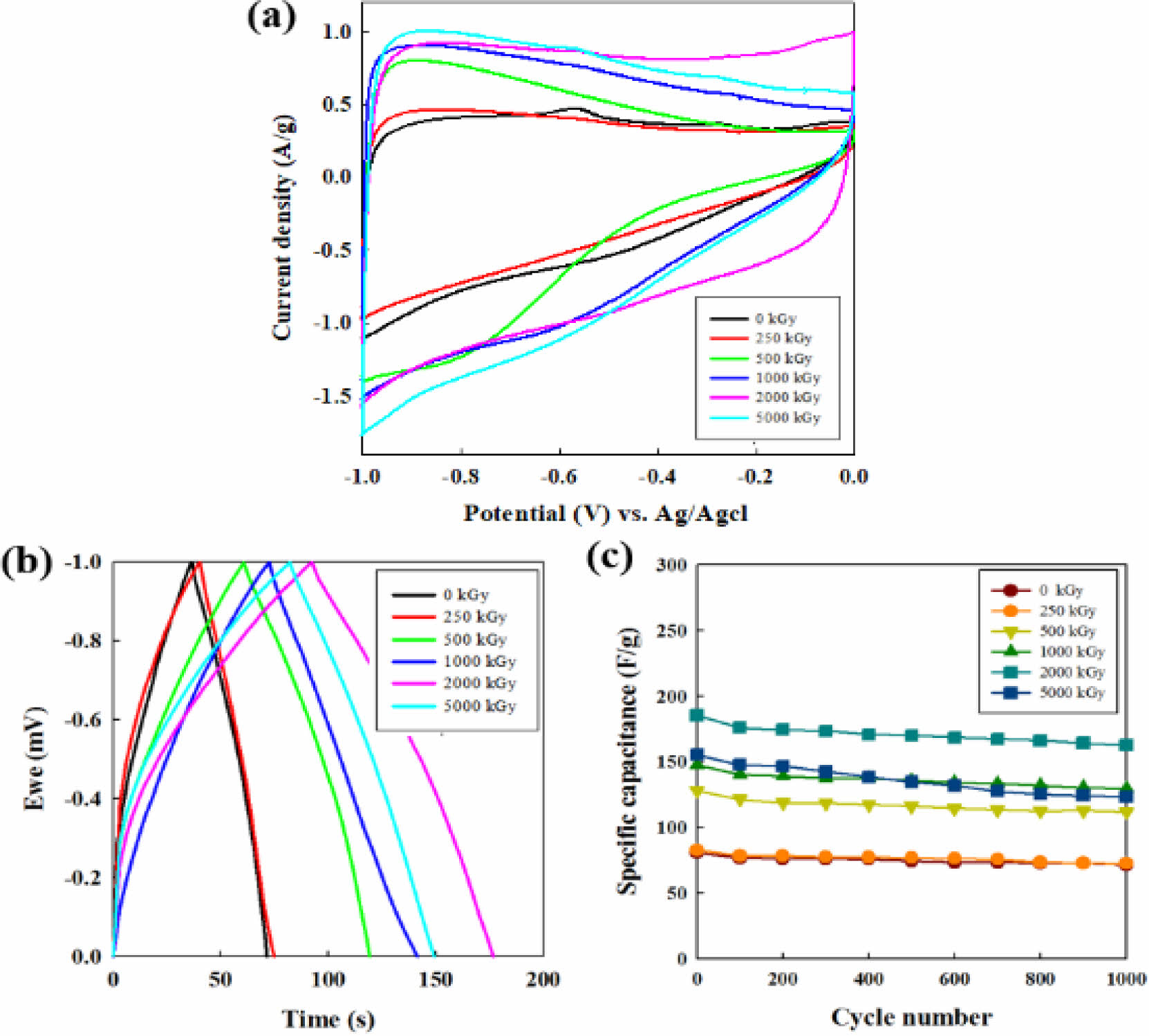
Electrochemical Properties of CNF Electrodes. The electrochemical behavior of all CNFs electrodes was evaluated by cyclic voltammetric analysis at a scan rate of 10 mV/s. As shown in Figure 6(a), the curve of the CNF electrode irradiated at 2000 kGy showed a quasi-rectangular shape, which means the unique accessibility of the ions of the aqueous electrolyte into the electrochemically active electrode surface and the excellent capacitive ability. Also, the largest integration area of the e-beam treated CNF electrode at 2000 kGy is the indicative of its high specific capacity, which can originate from its desirable surface area and micropore volume.29-31
The galvanostatic charge-discharge response is presented in Figure 6(c) at a current density of 1 A g-1 in 6 M KOH solution. The specific capacitance values of the samples, Cs (F/g), were evaluated from the electrochemical process according to the following equation,29

where I is the current (A), Δt is discharge time (s), ΔV is voltage variation in the time range measured (V) and m is the mass (g) of the electrodes. When the irradiation dose increases, the capacitance increases from 74.8 F g-1 (raw CNF) to 77.6 (250 kGy), 119.5 (500 kGy), 141.6 (1000 kGy), and 177.6 F g-1 (2000 kGy) in which the capacitance at 2000 kGy is enhanced by 237% of the pristine CNFs electrode. However, after the summit of the value, the capacitance fades to 149.3 F g-1 when the irradiation dose reaches 5000 kGy. In the carbon materials electrode, the surface area and microporous structure are key factors for the improvement of electrode capacity in an aqueous supercapacitor system.32
The cycling evolution of CNFs electrode capacitance shown in Figure 6(c) was conducted at a current density of 1 A g-1 for 1000 cycles in the galvanostatic mode. The cycle-life results of all irradiated CNF electrodes demonstrate robust cycle abilities compared to non-irradiated CNF electrode (0 kGy).
The specific capacitance of the non-irradiated CNF electrode retains 91% value after 100 cycles and thereafter reaches to the 71 F g-1 (88 %) after 1000 cycles. For all the CNF electrodes exposed from 250 to 2000 kGy, the specific capacitance retention is observed around 87% exhibiting the good cycle ability compared to the non-irradiated CNF. For the case of 5000 kGy, the specific capacitance is maintained by 79% (123.4 F g-1) over the entire cycles, indicating the poor cycle stability than that of CNF electrode below 2000 kGy.
|
Figure 1 SEM images of e-beam irradiated CNFs having different doses with (a) 0 kGy; (b) 250 kGy; (c) 500 kGy; (d) 1000 kGy; (e) 2000 kGy; (f) 5000 kGy. |
|
Figure 2 Diameter change of e-beam irradiated CNFs with various doses. |
|
Figure 3 FTIR spectra of CNFs exposed to (a) 0; (b) 250; (c) 500; (d) 1000; (e) 2000; (f) 5000 kGy of e-beam irradiation. |
|
Figure 4 XPS spectra of CNF exposed to (a) 0 kGy; (b) 250 kGy; (c) 500 kGy; (d) 1000 kGy; (e) 2000 kGy; (f) 5000 kGy of e-beam irradiation. |
|
Figure 5 (a) XRD profiles; (b) TGA thermograms; (c) Raman spectra; (d) ID/IG ratio of CNFs irradiated with increasing dose of ebeam. The ID/IG ratio was calculated from Raman spectra. |
|
Figure 6 (a) CV profiles at a scan rate of 10 mv/sec; (b) galvanostatic charge-discharge curves; (c) cycling performance of CNF electrodes with increasing e-beam irradiation from 0 to 5000 kGy at 1 A g-1 at 6 M KOH solution. |
In order to confirm the effect of e-beam irradiation as a technique for surface modification, PAN-based CNFs were prepared and different energy intensity of e-beam was applied. The e-beam treated CNFs were used as the electrode for a supercapacitor. The FTIR and XPS data confirmed that e-beam treatment caused the change of chemical bonds such as N-H and O-H, by breaking the original bonds of CNFs. The SEM and BET investigation proved that e-beam treatment enhanced the surface area and the pore volume of CNFs. Also, the decline of the structural robustness and the crystallinity of irradiated CNFs were investigated by TGA, XRD, and Raman analysis. Among the various CNFs, the irradiated CNFs with 2000 kGy showed the greater electrochemical result of 177. 6 F g-1 as a supercapacitor electrode than that of non-irradiated CNF (74.8 F g-1). These results suggest that the e-beam treatment is a simple and unique technique to enhance the surface and electrochemical properties of CNFs.
- 1. Chen, W. C.; Wen, T. C.; Teng, H. Polyaniline-deposited Porous Carbon Electrode for Supercapacitor. Electrochimica Acta 2003, 48, 641-649.
-

- 2. Kim, S. H.; Kim, Y. I.; Park, J. H.; Ko, J. M. Cobalt-Manganese Oxide/Carbon-nanofiber Composite Electrodes for Supercapacitors. Int. J. Electrochem. Sci. 2009, 4, 1489-1496.
- 3. Subbiah, T.; Bhat, G. S.; Tock, R.; Parameswaran, W. S.; Ramkumar, S. S. Electrospinning of Nanofibers. J. Appl. Polym. Sci. 2005, 96, 557-569.
-
- 4. Jang, J.; Bae, J.; Choi, M.; Yoon, S. Fabrication and Characterization of Polyaniline Coated Carbon Nanofiber for Supercapacitor. Carbon 2005, 43, 2730-2736.
-
- 5. Ryu, K. S.; Kim, K. M.; Park, N. G.; Park, Y. J.; Chang, S. H. Symmetric Redox Supercapacitor with Conducting Polyaniline Electrodes. J. Power Sources 2002, 103, 305-309.
-
- 6. Merino, C.; Soto, P.; Vilaplana-Ortego, E.; Gomez de Salazar, J. M.; Pico, F.; Rojo, J. M. Carbon Nanofibres and Activated Carbon Nanofibres as Electrodes in Supercapacitors. Carbon 2005, 43, 551-557.
-
- 7. Wangxi, Z.; Jie, L.; Gang, W. Evolution of Structure and Properties of PAN Precursors During Their Conversion to Carbon Fibers. Carbon 2003, 41, 2805-2812.
-
- 8. Ramakrishna, S.; Fujihara, K.; Teo, W.; Lim, T.; Ma, Z. An Introduction to Electrospinning and Nanofibers. World Scientific: Singapore, 2005.
-
- 9. Yoshii, F.; Zhanshan, Y.; Isobe, K.; Shinozaki, K.; Makuuchi, K. Electron Beam Crosslinked PEO and PEO/PVA Hydrogels for Wound Dressing. Radiat. Phys. Chem. 1999, 55, 133-138.
-
- 10. Zhong, S.; Teo, W.; Zhu, X.; Beuerman, R. W.; Ramakrishna, S.; Yung, L. An Aligned Nanofibrous Collagen Scaffold by Electrospinning and Its Effects on in Vitro Fibroblast Culture. J. Biomed. Mater. Res. Part A 2006, 79A, 456-463.
-
- 11. Zeng, J.; Aigner, A.; Czubayko, F.; Kissel, T.; Wendorff, J. H.; Greiner, A. Poly(vinyl alcohol) Nanofibers by Electrospinning as a Protein Delivery System and the Retardation of Enzyme Release by Additional Polymer Coatings. Biomacromolecules 2005, 6, 1484-1488.
-
- 12. Gibson, P.; Schreuder, H.; Rivin, D. Transport Properties of Porous Membranes Based on Electrospun Nanofibers. Colloid. Surface. A 2001, 187, 469-481.
-
- 13. Ramakrishna, S.; Jose, R.; Archana, P. S.; Nair, A. S.; Balamurugan, R.; Venugopal, J.; Teo, W. E. Science and Engineering of Electrospun Nanofibers for Advances in Clean Energy, Water filtration, and Regenerative Medicine. J. Mater. Sci. 2010, 45, 6283-6312.
-
- 14. Reneker, D. H.; Chun, I. Nanometre Diameter Fibres of Polymer, Produced by Electrospinning. Nanotechnology 1996, 7, 216-223.
-
- 15. Everhart, T. E.; Hoff, P. H. Determination of Kilovolt Electron Energy Dissipation vs. Penetration Distance in Solid Materials. J. Appl. Phys. 1971, 42, 5837-5846.
-
- 16. Bray, J. C.; Merrill, E. W. Poly(vinyl alcohol) Hydrogels. Formation by Electron Beam Irradiation of Aqueous Solutions and Subsequent Crystallization. J. Appl. Polym. Sci. 1973, 17, 3779-3794.
-
- 17. Sasuga, T.; Hayakawa, N.; Yoshida, K.; Hagiwara, M. Degradation in Tensile Properties of Aromatic Polymers by Electron Beam Irradiation. Polymer 1985, 26, 1039-1045.
-
- 18. Zhao, L.; Mitomo, H.; Zhai, M.; Yoshii, F.; Nagasawa, N.; Kume, T. Synthesis of Antibacterial PVA/CM-Chitosan Blend Hydrogels with Electron Beam Irradiation. Carbohydr. Polym. 2003, 53, 439-446.
-
- 19. Danelon, C.; Santschi, C.; Brugger, J.; Vogel, H. Fabrication and Functionalization of Nanochannels by Electron-Beam-Induced Silicon Oxide Deposition. Langmuir 2006, 22, 10711-10715.
-
- 20. Zang, J.; Bao, L.; Webb, R. A.; Li, X. Electron Beam Irradiation Stiffens Zinc Tin Oxide Nanowires. Nano. Lett. 2011, 11, 4885-4889.
-
- 21. Arshad, S. N.; Naraghi, M.; Chasiotis, I. Strong Carbon Nanofibers from Electrospun Polyacrylonitrile. Carbon 2011, 49, 1710-1719.
-
- 22. Zhang, X.; Kotaki, M.; Okubayashi, S.; Sukigara, S. Effect of Electron Beam Irradiation on the Structure and Properties of Electrospun PLLA and PLLA/PDLA Blend Nanofibers. Acta Biometer. 2010, 6, 123-129.
-
- 23. Sahoo, S.; Dhibar, S.; Hatui, G.; Bhattacharya, P.; Das, C. K. Graphene/Polypyrrole Nanofiber Nanocomposite as Electrode Material for Electrochemical Supercapacitor. Polymer 2013, 54, 1033-1042.
-
- 24. Chaukulkar, R. P.; Peuter, K.; Stradins, P.; Pylypenko, S.; Bell, J. P.; Yang, Y.; Agarwal, S. Single-Step Plasma Synthesis of Carbon-Coated Silicon Nanoparticles. Appl. Mater. Inter. 2014, 6, 19026-19034.
-
- 25. Esrafilzadeh, D.; Morshed, M.; Tavanai, H. An Investigation on the Stabilization of Special Polyacrylonitrile Nanofibers as Carbon or Activated Carbon Nanofiber Precursor. Synth. Met. 2009, 159, 267-272.
-
- 26. Lee, W. H.; Lee, J. G.; Reucroft, P. J. XPS Study of Carbon Fiber Surfaces Treated by Thermal Oxidation in a Gas Mixture of O2/(O2+ N2). Appl. Surf. Sci. 2001, 171, 136-142.
-
- 27. Blyth, R. I. R.; Buqa, H.; Netzer, F. P.; Ramsey, M. G.; Besenhard, J. O. XPS Studies of Graphite Electrode Materials for Lithium Ion Batteries. Appl. Surf. Sci. 2000, 167, 99-106.
-
- 28. Wang, Y.; Serrano, S.; Santiago-Aviles, J. J. Raman Characteri- zation of Carbon Nanofibers Prepared Using Electrospinning. Synth. Met. 2003, 138, 423-427.
-
- 29. Wang, K.; Huang, J.; Wei, Z. Conducting Polyaniline Nanowire Arrays for High Performance Supercapacitors. J. Phys. Chem. C 2010, 114, 8062-8067.
-
- 30. Wang, Y.; Shi, Z.; Huang, Y.; Ma, Y.; Wang, C.; Chen, M.; Chen, Y. Supercapacitor Devices Based on Graphene Materials. J. Phys. Chem. C 2009, 113, 13103-13107.
-
- 31. Su, F.; Poh, C. K.; Chen, J. S.; Xu, G.; Wang, D.; Li, Q.; Linb, J.; Lou, X. W. Nitrogen-Containing Microporous Carbon Nano- spheres with Improved Capacitive Properties. Energy Environ. Sci. 2011, 4, 717-724.
-
- 32. Kim, M.; Puthiaraj, P.; Qian, Y.; Kim, Y.; Jang, S.; Hwang, S.; Na, E.; Ahn, W.; Shim, S. E. High Performance Carbon Super- capacitor Electrodes Derived from a Triazine-Based Covalent Organic Polymer with Regular Porosity. Electrochim. Acta 2018, 284, 98-107.
-
- Polymer(Korea) 폴리머
- Frequency : Bimonthly(odd)
ISSN 0379-153X(Print)
ISSN 2234-8077(Online)
Abbr. Polym. Korea - 2022 Impact Factor : 0.4
- Indexed in SCIE
 This Article
-
2022; 46(5): 654-660
Published online Sep 25, 2022
- 10.7317/pk.2022.46.5.654
- Received on May 17, 2022
- Revised on Jun 28, 2022
- Accepted on Jul 18, 2022
Services
- Full Text PDF
- Abstract
- ToC
- Acknowledgements
- Conflict of Interest
Introduction
Experimental
Results and Discussion
Conclusions
- References
Shared
Correspondence to
- Sang Eun Shim
-
Department of Chemical Engineering, Inha University, 100 Inha-ro, Michuhol-gu, Incheon 22212, Korea
- E-mail: seshim@inha.ac.kr
- ORCID:
0000-0002-3678-6856
Hyecheon Building(Room 601), #354, Gangnam-Daero, Gangnam-Gu, Seoul 06242, Korea
TEL : 82-2-568-3860, 561-5203, 569-3860 FAX : 82-2553-6938 E-mail: polymer@polymer.or.kr