


- Analysis of the Mechanical Properties of Epoxy Resin Matrix Composites upon Multi-scale Synergistic Strengthening and Toughening
Keshan Liang, Xin Li*, **,†
 , Zhuo Wang***, Li Tang****, and Yujun Cao****
College of Intelligence Science and Technology, National University of Defense Technology, Changsha 410073, HuNan, P.R. China
*State Key Laboratory of Pulsed Power Laser Technology, Electronic Engineering Institute,
National University of Defense Technology, Hefei, 230037, AnHui, P.R. China
**Advanced Laser Technology Laboratory of Anhui Province, Hefei, 230037, AnHui, P.R. China
***HRG International Institute (He Fei) of Research and Innovation, Hefei, 230601, AnHui, P.R. China
****Academy of Hi-Tech Research, Hunan Institute of Traffic Engineering, Changsha 410003, HuNan, P.R. China- Multi-scale Synergistic Strengthening and Toughening에 따른 에폭시 수지 매트릭스 복합체의 기계적 특성 분석
Reproduction, stored in a retrieval system, or transmitted in any form of any part of this publication is permitted only by written permission from the Polymer Society of Korea.
A multi-scale synergistic modification technology is proposed to strengthen and toughen epoxy resin matrix composites, which can be used in the direct extrusion fabrication process. The toughness performance of epoxy resin matrix composites can be improved without compromising other advantages by adding micrometer- and nanometer-scale fillers to the matrix and optimizing the content of fillers, surface treatment process, dispersion method, and other parameters. We analyzed and discussed the mechanical properties of epoxy-based composites with micrometer-scale fillers, nanometer-scale fillers, and mixed multi-scale fillers. When 15 phr carbon fibers (15CFs), 6 phr rubber nanoparticles (6RNPs), and 1 phr carbon nanotubes (1CNTs) are added to epoxy resins (EPs), the tensile strength reached 91.6 MPa, 28.8% higher than that of the pure EPs; the achieved elastic modulus 4.72 GPa, 77.4% higher than the pure EPs; the fracture toughness was 2.97 MPa m1/2, 241.4% of the pure EPs, while the impact strength reached 63.4 kJ/m2, 369.6% higher than the pure EPs. The results show that the multi-scale reinforcements exhibit a synergistic effect on the strength and toughness of the composites.
By the multi-scale synergistic modification technology, such as adding micrometer- and nanometer-scale fillers to the matrix and optimizing the content of fillers, surface treatment process, dispersion method, and other parameters, the strength and toughness of epoxy resin matrix composites are improved without compromising other advantages.
Keywords: direct extrusion fabrication, carbon fibers, carbon nanotubes, rubber nanoparticles, mechanical properties.
The work was supported and financed by the National Natural Science Foundation of China (No.51875571), Anhui Natural Science Foundation of Youth Fund Project (Project No.2008085QF314), Projects of National University of Defense Technology (Project No.zk19-15) the Natural Science Foundation of Hunan Province (No. 2020JJ6091). These supports are gratefully acknowledged.
The authors would like to express their gratitude to EditSprings (https://www. editsprings.cn) for the expert linguistic services provided.
The authors declare that there is no conflict of interest.
Direct extrusion fabrication (DEF) is an additive manufacturing (AM) method that can directly, layer-by-layer, produce complex 3D structures based on CAD files without the need for special processing of single parts, heating, and manual intervention.1-4 Theoretically, DEF can use any pasty or gel-like composite, given that it can keep its shape and has enough self-support to avoid collapsing.
Thermosetting epoxy resin (EP)-based composites (TERCs) exhibit many distinctive advantages, such as lightweight, chemical stability, and good mechanical properties.5-8 Consequently, they gradually replace metallic materials and are widely used in the aerospace, aviation, automobile, and electronics industry, and also in many other fields. Compared with photocurable and thermoplastic resins, the elastic modulus of TERCs is much higher when they are used in an AM process. The disadvantages of EPs are mainly related to their brittle fracture (the fracture toughness is 0.87 MPa·m1/2) and poor resistance to crack growth (the impact strength is 13.5 kJ/m2), which hinder their wide industrial applications.9 Therefore, many modification methods have been proposed to improve the mechanical properties of resin matrix composites, including micrometer-scale and nano-scale reinforcing modifications.9-11
Carbon fibers (CFs) are among the most commonly used micrometer-scale fillers for epoxy resins due to their low density, high specific strength, and high specific modulus. Kaynak et al. found that the elastic modulus and impact strength of the polyamide-6/carbon fiber composites increased upon the addition of micrometer-scale CF, while their elongations at break decreased.12 Carbon nanotubes (CNTs), which discovery is related to fullerene chemistry, exhibit a special structure, consisting of 2-50 layers of coaxial circular tubes composed of carbon atoms arranged in a hexagonal shape.13,14 Due to their excellent mechanical properties, electrical conductivity, and heat transfer properties, CNTs are widely used in scientific research and engineering practice.15,16 CNTs also show a huge aspect ratio (the radial dimension is on the nanometer level, while the axial dimension is on the micrometer level) and great specific surface areas, endowing them with excellent stress transfer ability.17,18 Therefore, CNTs are often selected as a second microphase material for modified resins.
However, neither CFs nor CNTs can effectively improve the fracture toughness of TERCs. It was reported that inorganic micrometer-scale and nanometer-scale particles significantly improve the fracture toughness of epoxy resin. The addition of nanosilica-rubber core-shell nanoparticles increased the overall mechanical properties of the epoxy system, where the impact strength was improved by 39.4% with a loading of 2 wt.% of the nanofiller.19 In recent years, rubber nanoparticles (RNPs) have been increasingly used in TERCs to improve mechanical properties. Furthermore, reactive RNPs and organically modified nanoclay were applied to toughen the epoxy matrix.20 However, with the introduction of the RNP phase, elastic modulus, tensile strength, and other properties may decrease substantially, so the main challenge in the TERC toughening is improving the toughness without sacrificing other properties. Su et al. found that RNPs can effectively improve the fracture toughness of epoxy asphalt binder.21 Ma et al. reported that in situ formed RNPs greatly enhanced the fracture energy of epoxy resin (from 140 to 840 J/m2), with only a slight decrease in elastic modulus (from 2.85 to 2.49 GPa).22
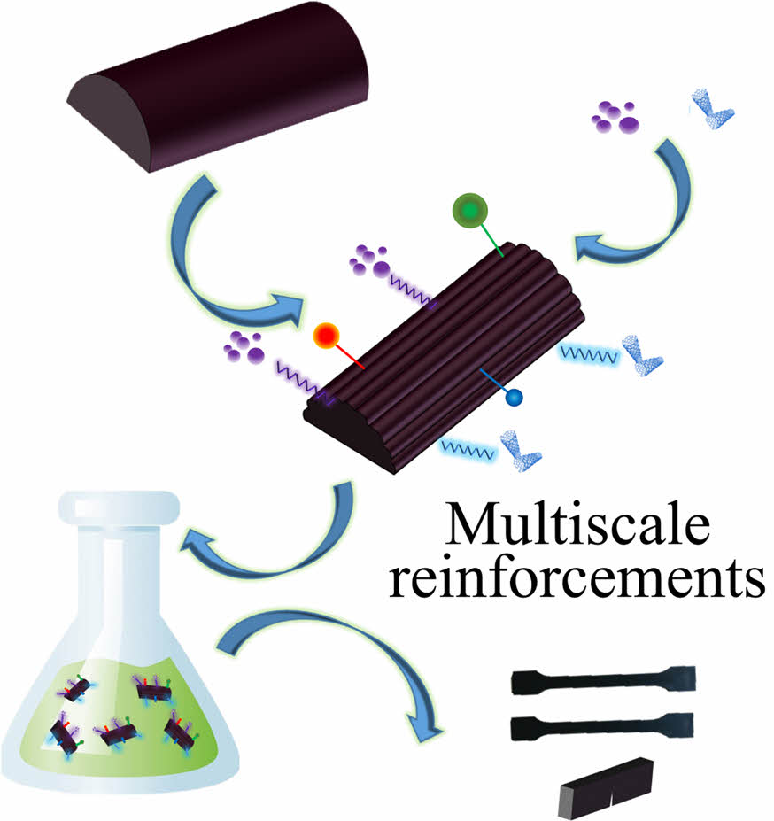
Rahmanian et al. showed evident enhancement in the comprehensive mechanical performance, i.e., tensile, flexural, and impact properties, of the composites of polypropylene reinforced with both CNTs and CNT-grown CFs, indicating a synergistic effect of CNTs.23 Zhang et al. and Sharma et al. indicated the synergistic effect of multi-scale structures of epoxy matrix-based materials reinforced with carbon nanofibers and short carbon fibers on the strength and fracture properties.24,25 In this paper, micrometer- and nanometer-scale reinforcements were adopted to modify the epoxy resin matrix. The surface of CFs was treated by chemical oxidation and sonication to improve its roughness and binding to the matrix material. The research has shown, different proportions of reinforcements can mutually compensate and show a complementary effect. Short CFs, RNPs, and CNTs were used as reinforcements in the current work, and the synergistic effect of multi-scale reinforcements on tensile strength, fracture toughness, and impact strength was analyzed and discussed. We also assessed the fracture mechanism by scanning electron microscopy and showed the particular effect of nanometer-scale reinforcements. The paper provides promising results for future DEF.
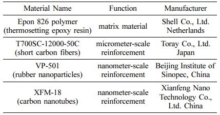
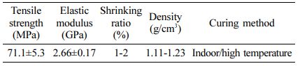
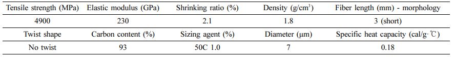
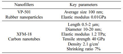
Materials and Methods. Table 1 shows the materials used in this paper, while their detailed parameters are listed in Tables 2, 3, and 4.
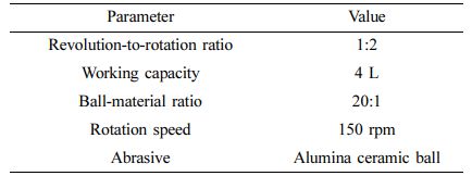
CFs adopted in this paper have been surface-treated to improve the interfacial bonding between reinforcements and matrix materials. As amorphous carbon and the sizing agent are present on the surface of CFs, the CFs were firstly milled for 15 min in a planetary ball mill (QM-ISP4, Nanjing University Instrument Plant) to remove these phases, and the following working parameters were used (Table 5).
According to the size and hardness characteristics of CFs, a three-stage ball milling method was selected – the mass ratio of the large balls (20 mm), medium balls (10 mm), and small balls (5 mm) was 1:2:1. It was empirically proven that the EP matrix can benefit from the reinforcing effect only when the average length of CFs exceeds 500 μm. The average length of CFs is inversely proportional to the milling time. After 15 min, the average length of CFs was 885 μm, and this sample was designated as sample A. When the milling time was 60 min, having the other parameters unchanged, the average length was 143 μm, and the sample was designated as sample B.
Afterward, both A and B samples were put into a Soxhlet extractor for 48 h with acetone. After cleaning and drying, they were placed in HNO3 (65 vol%) for sonication for 2 h. Next, the samples were put into a coupling agent (KH550, 25 vol%) for 1 h. Finally, the treated CFs were washed until neutralization with deionized water and dried in an oven at a temperature of 80 ℃. Thus, sample A’ and B’ are obtained.
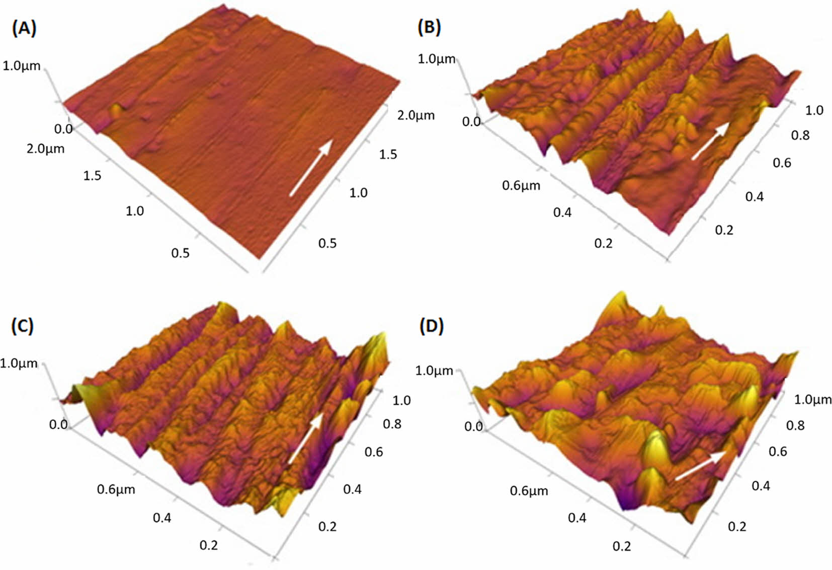
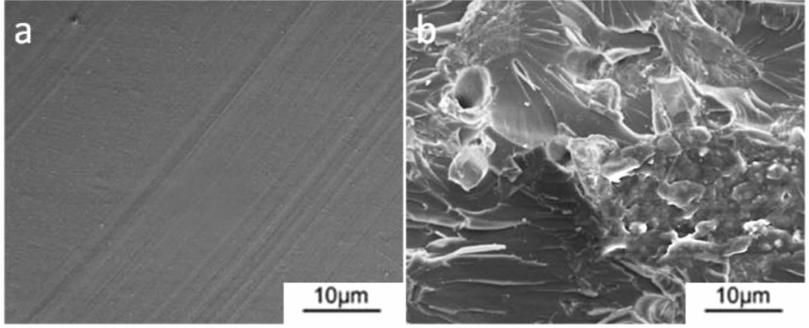
Figure 1 shows the surface morphology of the CFs sample. For untreated CFs, the surface is relatively smooth, showing only several relatively shallow and wide longitudinal grooves, with a surface roughness (RMS) of 54.5 nm. However, after 15 min milling, Figure 1(b), sample A shows that the shallow and wide grooves are replaced by deep and narrow grooves, with a surface roughness (RMS) of 168.7 nm. The sizing agent and amorphous carbon on CFs of the sample A are peeled off during the ball milling process. When sample A is further treated by liquid-phase oxidation and sonication (call it Sample A’), the width of the surface groove increases to 0.15-0.3 μm, and the RMS increases to 396.8 nm, but the longitudinal texture on the CFs surface is still integrated (Figure 1(c)). However, after the same treatment, the surface of sample B has been significantly eroded and destroyed (Figure 1(d)), exhibiting greatly reduced strength due to the destroyed surface, and the RMS value is 614.1 nm.
The main elements on the surface of CFs before and after the surface treatment are C and O, with a small amount of N (see Table 6) were determined using an EDS spectrometer (FEI-QUANTA200). Si is detected in the modified sample A’ because the sample is immersed in the aqueous solution of the silane KH550 coupling agent with a concentration of 25% for 1 h. Table 6 shows the atomic concentration before and after the surface modification of CFs. After modification, the concentrations of C and N decrease while the concentration of O increases. The increase of the oxygen-carbon ratio indicates that the surface of CFs is oxidized after ball milling, liquid-phase oxidation, and sonication, which improves its surface activity.
In addition, after sonication and liquid-phase oxidation, -OH radicals and H2O2 are produced. They induce a strong oxidation effect on the surface of CFs and increase the specific surface area and the amount of O-containing functional groups of CFs, which can greatly improve the interface binding between CFs and the EP matrix, making a strong connection between the two phases after curing. Moreover, the rough surface of CFs favors the in-flow of the matrix material into the grooves upon mixing, forming strong mechanical interlocking after curing.
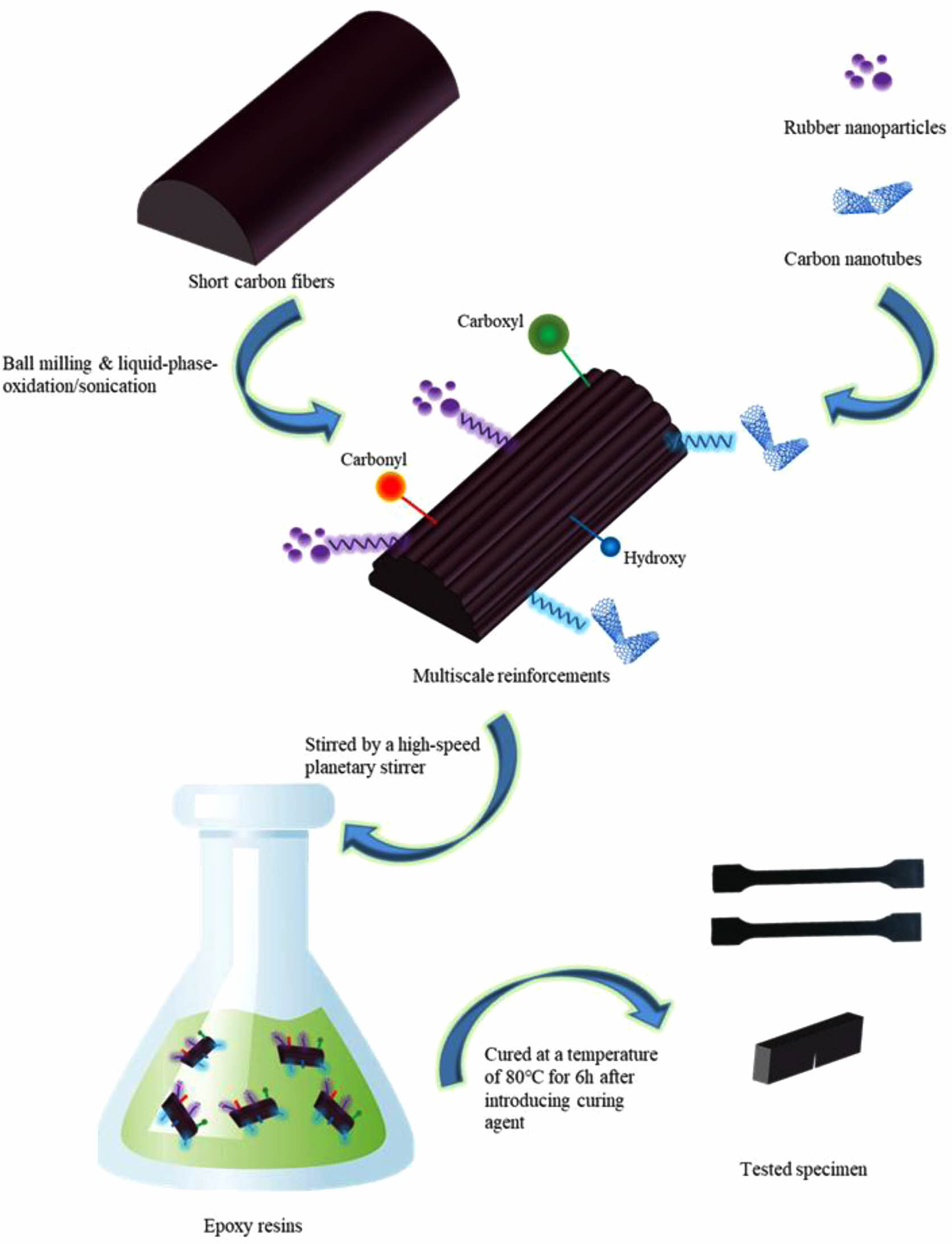
After the surface modification, the modified CFs were placed into EP and then mixed by an ultrahigh-speed planetary blender for 5 h at a speed of 3000 rpm; afterward, CNTs and RNPs were added into the mixture and sonicated for 0.5 h at 25 ℃. Afterward, the curing agent was introduced into the blend (stirring for another 3 h), and the system was cured at 80 ℃ for 6 h. Finally, the samples were cooled to room temperature (the whole process is depicted in Figure 2).
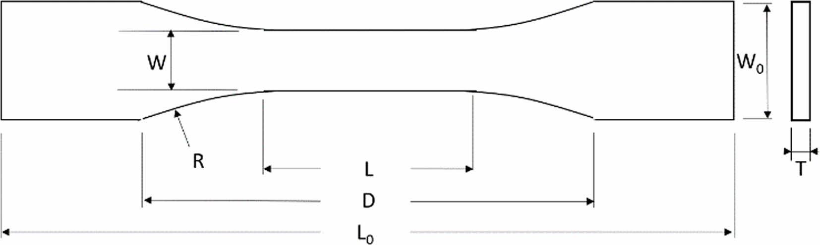
The test of tensile properties was performed using a SANS CMT5105 universal material testing machine. The test process was based on the ASTM D638-2010 standard, Figure 3 is the sketch of specimen. The test temperature was 25 ℃, and the tensile speed was 5 mm/min. 5 specimens at least were tested from each group of specimens, which were tempered at 60 ℃ for 30 min before testing.
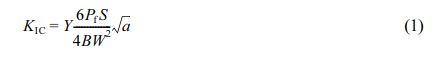
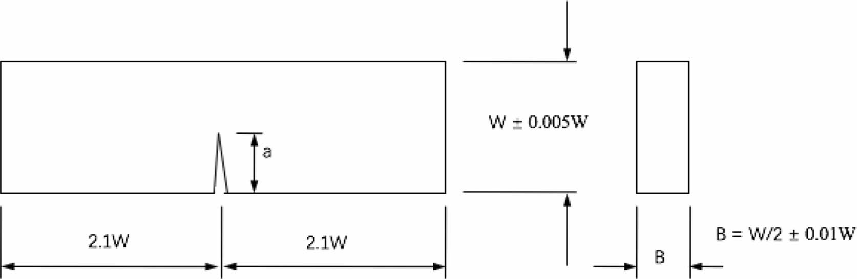
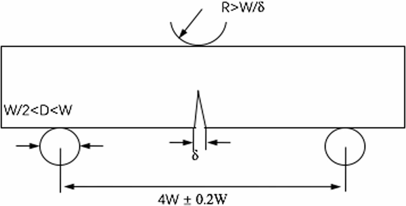
The fracture toughness test was performed following the ASTM E-399 standard and the national GB4161-84 standard using the single-edge notched beam method (SENB). The test specimen size was 42 mm × 10 mm × 5 mm, and it was cured in a steel mold. Before the test, the surface of the specimen was sanded to avoid artificial defects. The test speed was 5 mm/min. Figure 4 shows the schematic representation of the specimen. According to the standard requirements, the height W and thickness B of the specimen should satisfy the relationship of W/B = 2, and the crack length a should satisfy the relationship of a/W = 0.45-0.55. The specimen should ensure the flatness, perpendicularity, and parallelism between the planes, and the perpendicularity between the notch and the bottom surface should be within ±2° to provide the testing accuracy. Figure 5 is the schematics of measurement according to the standard.
The fracture toughness in this paper was calculated in terms of KIC. In eq. (1), Y represents the shape factor of the cracks, S is the support length at the bottom, B is the thickness of the specimen, W is the specimen height, and a represents the crack length.26 Poisson’s ratio is 0.35.27
|
Figure 1 Surface morphology of CFs after different surface treatments: (a) untreated sample, (b) sample A, (c) sample A after liquid-phase oxidation and sonication, and (d) sample B after liquidphase oxidation and sonication. |
|
Figure 2 The preparation process of multiscale-reinforced composites. |
|
Figure 3 Specimen size according to the ASTM D638-2010 standard.26 |
|
Figure 4 Schematic representation of the specimen according to the ASTM E-399 standard and the national GB4161-84 standard. |
|
Figure 5 Schematic representation of the measurement according to the ASTM E-399 standard and the national GB4161-84 standard |
|
Table 5 Set of the Working Parameters Used for the Ball-milling Surface Treatment of CFs |
|
Table 6 Elemental Content on the Surface of CFs Before and After the Surface Treatment |
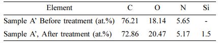
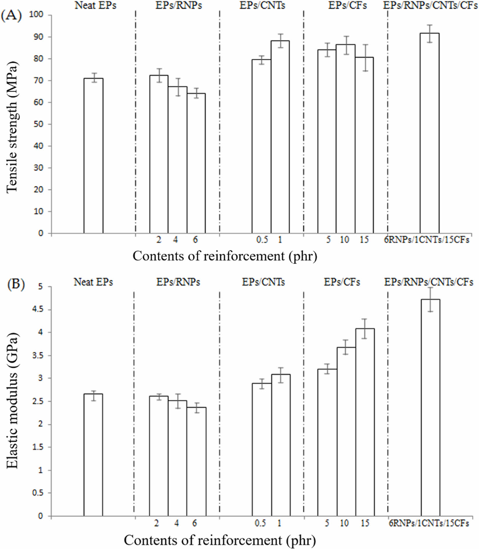
Figure 6 shows the elastic modulus and tensile strength of the composites with different proportions of reinforcements. The CFs after the ball milling and liquid-phase oxidation ultrasonic treatment exhibit an obvious reinforcement effect on the tensile strength of EPs. For the composite sample with 10 phr CFs, tensile strength is 21.5% higher than that of pure EPs. Compared with the single-scale reinforced composites, the multi-scale reinforced composites exhibit even a more significant improvement in tensile strength. When 15 phr CFs (15CFs), 6 phr RNPs (6RNPs), and 1 phr CNTs (1CNTs) are added to EPs, tensile strength reaches the highest value of 91.6 MPa, which is 28.8% higher than that of the pure EPs. It is slightly greater than the sum of adding 6RNPs (9.7% lower than that of pure EPs), 1CNTs (24.1% higher than that of pure EPs), and 15CFs (13.4% higher than that of pure EPs). This shows that different reinforcements display a synergistic effect on the tensile strength of epoxy-based composites.
In terms of elastic modulus, similar to tensile strength, multi-scale reinforcements also exhibit a synergistic effect. The elastic modulus of the composites (15CFs/1CNTs/6RNPs) is 4.72 GPa (77.4% higher than that of pure EPs), which is larger than the sum of adding 6RNPs (10.9% lower than that of pure EPs), 1CNTs (16.2% higher than that of pure EPs), and 15CFs (53.8% higher than that of pure EPs).
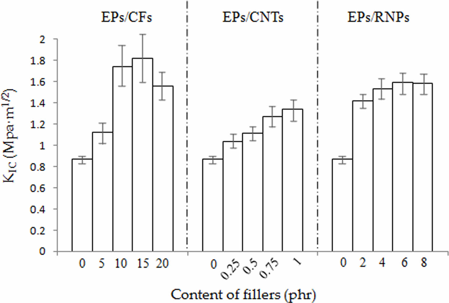
Figure 7 shows the fracture toughness of single-scale filler-reinforced composites with different amounts of reinforcement. The reinforced composites (15CF, 1CNT, 6RNP) exhibit better fracture toughness than EP. Compared with the fracture toughness of neat EPs, the KIC is 0.87 MPa·m1/2, and the fracture toughness of the composites with single-scale fillers is improved. Although the fracture toughness increment of 1CNTs is far less than 15CFs, the content of CFs is 15 times higher than that of CNTs, indicating that CNTs have higher toughening efficiency on EPs, when normalized on the added amount, than the micrometer-sized CFs.
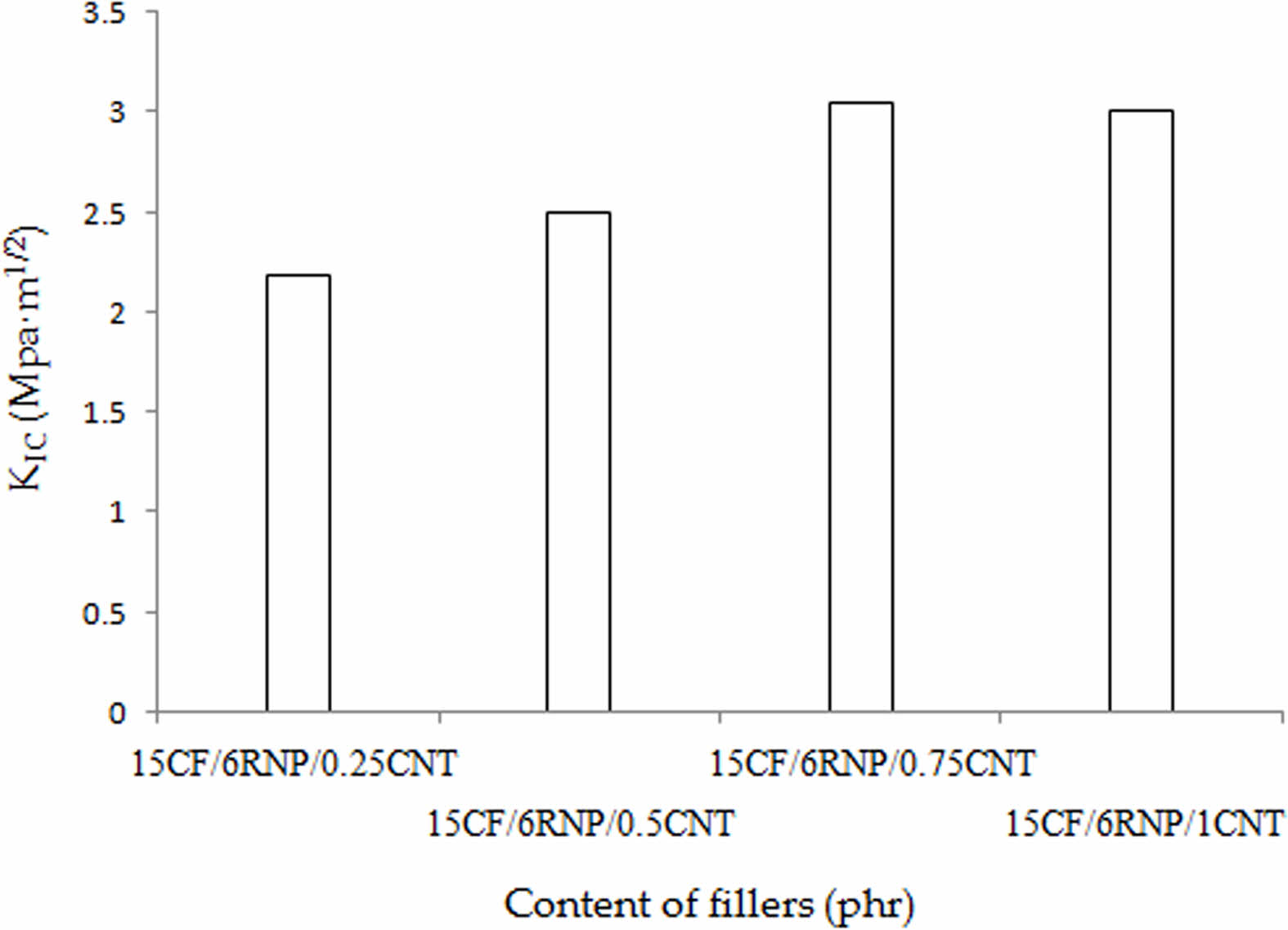
Figure 8 shows the fracture toughness of various multi-scale filler-reinforced composites. The multi-scale reinforced specimens with CFs, CNTs, and RNPs show a synergistic enhancement in fracture toughness compared with the specimens solely reinforced by CFs, RNPs, or CNTs. With 15 phr CFs and 6 phr RNPs, the KIC of 15CF/6RNP/0.75CNT reaches 3.04 MPa·m1/2, which is 349.4% higher than that of neat EP. When increasing the content of CNTs or RNPs, the KIC value also increases. In other words, the combined reinforcements exceed the effect of solely filled composites on fracture toughness. Therefore, CFs, RNPs, and CNTs exhibit synergetic effects on the toughness performance of the EPs.
Figure 9 shows the SEM micrographs of the fracture surfaces of neat and multi-scale reinforced EPs with 15CF/6RNP/0.75CNT. The neat EP specimen shows a smooth fracture surface, Figure 9(a), indicating a brittle fracture. After adding CFs, RNPs, and CNTs reinforcements, a much rougher fracture surface appears, with apparent plastic deformation areas (Figure 9(b). On the one hand, nanometer-scale fillers have a larger specific surface area than micrometer-scale fillers, so they can help improve the stress transfer ability. On the other hand, because the dimension of nanometer-scale fillers is much smaller than that of micrometer-scale fillers, debonding and pullout mechanisms are more pronounced, implying that nanometer-scale fillers can help prevent the crack propagation inside the composites.
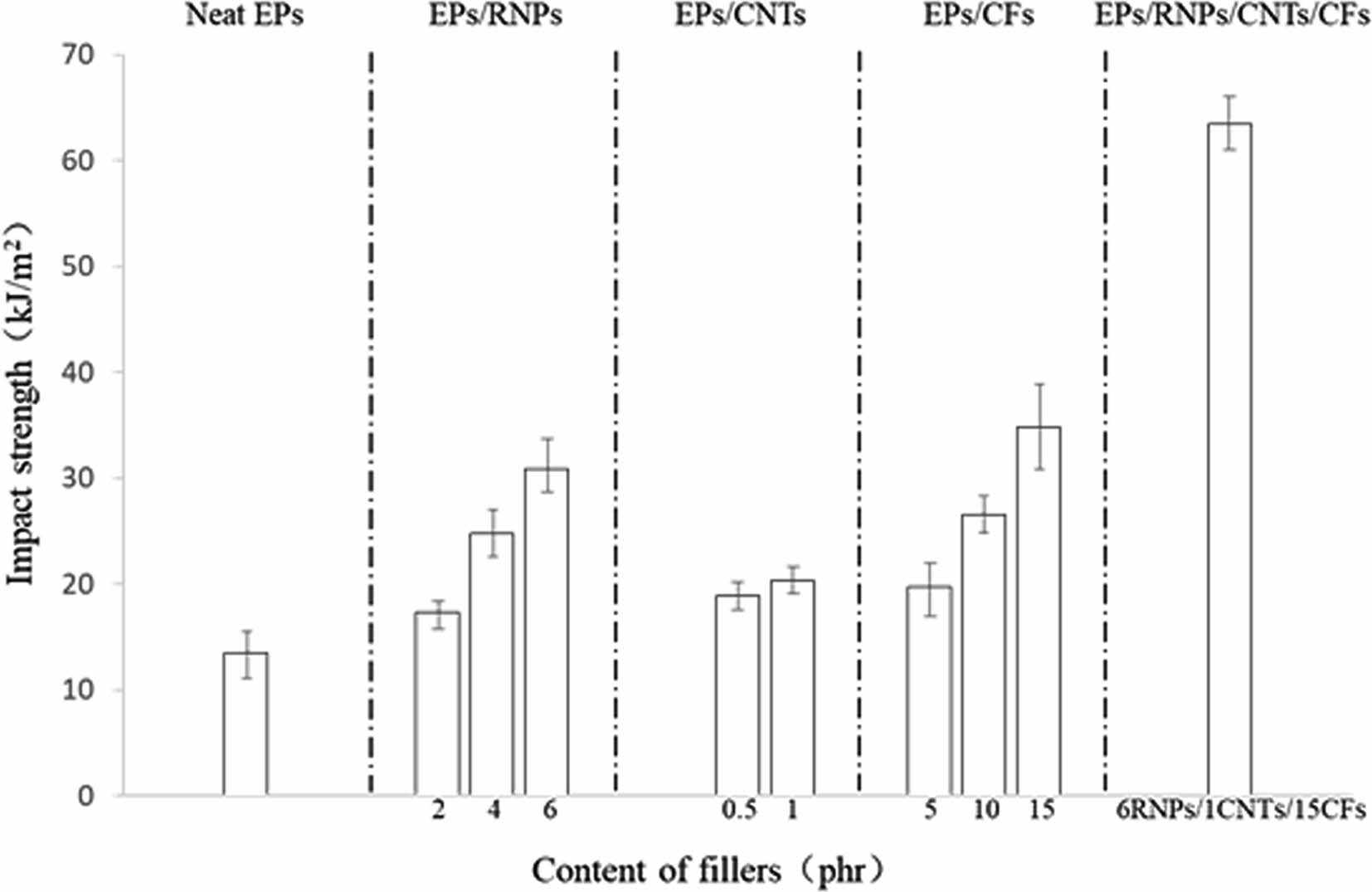
Figure 10 shows the impact strength of the composites with different fillers (unnotched specimens were adopted). The impact strength of the neat EP is 13.5 kJ/m2, and it increases when RNPs, CNTs, and CFs are solely added.
Similarly, CFs, RNPs, and CNTs exhibit a synergistic effect on the impact strength of TERCs. The impact strength of the composites with 6RNPs/1CNTs/15CFs is 63.4 kJ/m2, which is 369.6% higher than that of the net EP. The impact strength of materials mainly depends on two factors: the resistance to crack generation and the inhibition of crack growth. Adding nanometer-scale fillers after CFs can provide a more uniform internal stress distribution of the composite and reduce the probability of crack growth between the matrix and CFs. Moreover, due to the large difference in size, the nanometer-scale fillers are evenly attached to the surface of CFs, so they can reduce the stress concentration at the interface between the matrix and CFs, effectively inhibiting the crack propagation.
|
Figure 6 Tensile strength and elastic modulus of EPs with different contents of reinforcement. |
|
Figure 7 Fracture toughness of single-scale filler-reinforced composites with different amounts of reinforcement (solely filled). |
|
Figure 8 Fracture toughness of EPs with different contents of reinforcement (multi-scale reinforced). |
|
Figure 9 SEM micrographs of the fracture surfaces: (a) neat EP; (b) EP multi-scale reinforced with 15CF/6RNP/0.75CNT. |
|
Figure 10 Impact strength of the neat EP and EPs with different contents of single-scale and multi-scale fillers. |
The effects of multi-scale reinforcing fillers on the strengthening and toughening of thermosetting epoxy matrix composites were studied. The tensile strength, elastic modulus, fracture toughness, and impact strength of the composites significantly increased by adding micrometer-scale CFs and nanometer-scale CNTs and RNPs fillers to the epoxy matrix. The study found that when 15phr CFs (15CFs), 6phr RNPs (6RNPs), and 1phr CNTs (1CNTs) were added to EPs, the tensile strength, elastic modulus, fracture toughness, and impact strength of the composite were 28.8, 77.4, 141.4, and 369.6% higher, respectively, than those of the pure EPs.
The use of micrometer-scale fillers (CFs) modified the pure EPs can significantly improve the mechanical properties. However, the thermal expansion coefficients of CFs and EPs are very different, so that there is a large internal stress at the interface between CFs and matrix, which limits the mechanical properties of the composite.
After continuing to add the nanometer-scale fillers (CNTs, RNPs), the mechanical properties of the composite have been further improved. Compared with CFs, (1) the nanometer-scale filler is smaller, which improves the interface between CFs and matrix, and reduces the probability of cracks between matrix and CFs; (2) The specific surface area of the nanometer-scale filler is larger, which has better stress transfer ability and improves the distribution of stress in the composite; (3) The nanometer-scale filler increases the roughness of CFs, hinders fiber debonding and fiber pull-out, and achieves the toughening effect of composite materials; (4) The nanometer-scale filler is uniformly attached to the surface of CFs, which reduces the stress concentration at the interface between the matrix and CFs, inhibits the propagation of cracks.
In summary, the micrometer- and nanometer-scale reinforcements exhibited a strong synergistic effect on the mechanical properties of epoxy matrix composites, demonstrating a successful material preparation method for direct extrusion manufacturing.
- 1. Beaman, J. J.; Barlow, J. W.; Bourell, D. L.; Crawford, R. H.; Marcus, H. L.; McAlea, K. P. Solid Freeform Fabrication: A New Direction in Manufacturing; Springer: New York, 1997.
-

- 2. Shaikh, S.; Kumar, N.; Jain, P. K.; Tandon, P. Hilbert Curve Based Toolpath for FDM Process. In CAD/CAM, Robotics and Factories of the Future, Mandal, D. K., Syan, C. S., Eds.; Springer: New Delhi, 2016, pp 751-759.
-
- 3. King, B. H.; Dimos, D.; Yang, P.; Morissette, S. L. Direct-write Fabrication of Integrated, Multilayer Ceramic Components. J. Electroceram.,1999, 3, 173-178.
-
- 4. Hsiao Chuan Yen. Experimental Studying on Development of Slurry-layer Casting System for Additive Manufacturing of Ceramics. Int. J. Adv. Manuf. Technol.2015, 77, 915-925.
-
- 5. Khshain, N. T.; Al-Mahaidi, R.; Abdouka, K. Modelling of Near-surface Mounted Carbon Fibre Reinforced Polymer Strips Embedded in Concrete with Cement-based Adhesive. Compos. Struct., 2015, 132, 205-214.
-
- 6. Todoroki, A.; Kumagai, K.; Matsuzaki, R. Foldable GFRP Boat Using Partially Flexible Composites. Proceedings of SAMPE 2008/Multifunctional Materials: Working Smarter Together, Memphis, Tennessee, Sept 8-11, 2008, 7292, 72923A-72923A-10.
- 7. Ejserholm, F.; Stegmayr, J.; Bauer, P.; Johansson, F.; Wallman, L.; Bengtsson, M.; Oredsson, S. Biocompatibility of a Polymer Based on Off-Stoichiometry Thiol-Enes + Epoxy (OSTE+) for Neural Implants. Biomaterials Res., 2015, 19, 1-10.
-
- 8. Spee, T.; Timmerman, J. G.; Ruhl, R.; Kersting, K.; Heederik, D. J. J.; Smit, L. A. M. Determinants of Epoxy Allergy in the Construction Industry: a Case-control Study, Contact Dermatitis, 2016, 74, 259-266.
-
- 9. Domun, N.; Hadavinia, H.; Zhang, T. Improving the Fracture Toughness and the Strength of Epoxy Using Nanomaterials – a Review of the Current Status. Nanoscale, 2015, 7, 10294-10329.
-
- 10. Zhao, S.; Wang, Z.; Guo, J.; Yang, B. Effect of Hybrid Style on the Performance of CF/GF/epoxy Hybrid Composites Subjected to Low-velocity Impact. J. Harbin Eng. Univ. 2015, 36, 1476-1480.
- 11. Chai, H.; Tang, X. B.; Chen, F. D.; Chen, D. Preparation and Performance of New Type Flexible Neutron Shielding Composites. Atmoic Energy Sci. Technol. 2014, 48, 839-844.
- 12. Kaynak, C.; Orgun, O.; Tincer, T. Mechanical Properties, Crystallization and Melting Behaviors of Carbon Fiber-reinforced PA6 Composites. Polym. Test., 2005, 24, 455-462.
-
- 13. Kroto, H. W.; Heath, J. R.; O'Brien, S. C.; Curl, R. F.; Smalley, R. E. C60 : Buekminsteffullerene. Nature, 1985, 318, 163-163.
-
- 14. Iijima, S.; Helical Microtubules of Graphitic Carbon. Nature, 1991, 354, 56-58.
-
- 15. Ajayan, P. M. Nanotubes from Carbon. Chem. Revi., 1999, 99, 1787-1799.
- 16. Paradise, M.; Goswami, T. Carbon Nanotubes – Production and Industrial Applications. Materials and Design, 2007, 28, 1477-1489.
-
- 17. Martone, A.; Formicola, C.; Giordano, M.; Zarrelli, M. Reinforcement Efficiency of Multi-Walled Carbon Nanotube/Epoxy Nano Composites. Compos. Sci. Technol., 2010, 70, 1154-1160.
-
- 18. Saurín, N.; Sanes, J.; Bermúdez, M. D. Effect of Graphene and Ionic Liquid Additives on the Tribological Performance of Epoxy Resin. Tribol. Lett., 2014, 56, 133-142.
-
- 19. Liu, S. L.; Fan, X. S.; He, C. B. Improving the Fracture Toughness of Epoxy with Nanosilica-rubber Core-shell Nanoparticles. Compos. Sci. Technol., 2016, 125, 132-140.
-
- 20. Mona, A. A.; Usama, F. K.; Neviene, O. S.; Ahmed, I. H. The Overall Effect of Reactive Rubber Nanoparticles and Nano Clay on the Mechanical Properties of Epoxy Resin. J. Radiat. Res. Appl. Sci., 2015, 8, 549-561.
-
- 21. Su, W. F.; Han, X. C. H.; Gong, J.; Xi, Z. H.; Zhang, J. S. H.; Wang, Q. J.; Xie, H. F. Toughening Epoxy Aphalt Binder Using Core-shell Rubber Nanoparticles. Constr. Build. Mater., 2020, 258, 119716.
-
- 22. Ma, J.; Mo, M.; Du, X. S.; Rosso, P.; Friedrich, K.; Kuan, H. C. H. Effect of Inorganic Nanoparticles on Mechanical Property, Fracture Toughness and Toughening Mechanism of Two Epoxy Systems. Polymer, 2008, 49, 3510-3523.
-
- 23. Rahmanian, S.; Suraya, A. R.; Shazed, M. A.; Mohd Salleh, M. A.; Yusoff, H. M. Carbon and Glass Hierarchical Fibers: Influence of Carbon Nanotubes on Tensile, Flexural and Impact Properties of Short Fiber Reinforced Composites. Mater. Des., 2013, 43, 10-16.
-
- 24. Zhang, G.; Karger-Kocsis, J.; Zou, J. Synergetic Effect of Carbon Nanofibers and Short Carbon Fibers on the Mechanical and Fracture Properties of Epoxy Resin. Carbon, 2010, 48, 4289-4300.
-
- 25. Sharma, S. P.; Lakkad, S. C. Compressive Strength of Carbon Nanotubes Grown on Carbon Fiber Reinforced Epoxy Matrix Multi-scale Hybrid Composites. Surf. Coat. Technol., 2010, 205, 350-355.
-
- 26. ASTM D 638-2010. Standard Test Methods for Tensile Properties of Plastics. ASTM International: West Conshohocken, PA, 1999.
- 27. Kinloch, A. J. Adhesion and Adhesives: Science and Technology; Chapman and Hall: London, 1987.
- Polymer(Korea) 폴리머
- Frequency : Bimonthly(odd)
ISSN 0379-153X(Print)
ISSN 2234-8077(Online)
Abbr. Polym. Korea - 2023 Impact Factor : 0.4
- Indexed in SCIE
 This Article
-
2023; 47(2): 143-150
Published online Mar 25, 2023
- 10.7317/pk.2023.47.2.143
- Received on Oct 19, 2022
- Revised on Nov 13, 2022
- Accepted on Dec 13, 2022
Services
- Full Text PDF
- Abstract
- ToC
- Acknowledgements
- Conflict of Interest
Introduction
Experimental
Results and Discussion
Conclusions
- References
Shared
Correspondence to
- Xin Li
-
*State Key Laboratory of Pulsed Power Laser Technology, Electronic Engineering Institute,
National University of Defense Technology, Hefei, 230037, AnHui, P.R. China
**Advanced Laser Technology Laboratory of Anhui Province, Hefei, 230037, AnHui, P.R. China - E-mail: lixinkiller@nudt.edu.cn
- ORCID:
0000-0001-9040-7194
Hyecheon Building(Room 601), #354, Gangnam-Daero, Gangnam-Gu, Seoul 06242, Korea
TEL : 82-2-568-3860, 561-5203, 569-3860 FAX : 82-2553-6938 E-mail: polymer@polymer.or.kr