


- Investigation on Wear Behavior of PETG and PLA Parts Fabricated with Fused Deposition Modelling Under Different Wear Conditions
Gökmen Atlıhan†

Department of Mechanical and Manufacturing, Pamukkale University, 20400, Turkey
- 용융 적층 모델링 방법으로 가공된 PETG와 PLA의 마모 거동 연구
Reproduction, stored in a retrieval system, or transmitted in any form of any part of this publication is permitted only by written permission from the Polymer Society of Korea.
Polyethylene terephthalate glycol (PETG) has been widely used in the production of industrial parts with additive manufacturing due to its high strength and temperature performance. In this study, the abrasive wear behavior of PETG specimens produced by the fused deposition modelling (FDM) method was characterized under different wear conditions (3 different sliding speeds and loads). Poly lactic acid (PLA), which is widely used in additive manufacturing with FDM, has been examined for comparison purposes. Experimental results showed that PETG specimens showed the best abrasion resistance in all abrasion conditions. Different parameters were used in wear conditions. It was determined that the wear behavior of PETG could be optimized. PETG samples had the lowest coefficient of friction. Worn surface analysis results showed that micro-cutting, abrasive wear, and delamination wear mechanisms are active wear mechanisms.
Polyethylene terephthalate glycol (PETG) has been widely used in the production of industrial parts with additive manufacturing due to its high strength and temperature performance. In this study, the abrasive wear behavior of PETG specimens produced by the fused deposition modelling (FDM) method was characterized under different wear conditions (3 different sliding speeds and loads). PLA, which is widely used in additive manufacturing with FDM, has been examined for comparison purposes. Experimental results showed that PETG specimens showed the best abrasion resistance in all abrasion conditions. Different parameters were used in wear conditions. It was determined that the wear behavior of PETG could be optimized.
Keywords: polyethylene terephthalate glycol, fused deposition modelling, tribological colors, additive manufacturing, poly lactic acid.
This work was supported by the Pamukkale University Scientific Research Project with project number of 2019HZDP010 and the authors of this study would like to thank to the Pamukkale University for financial support.
The authors declare that there is no conflict of interest.
In the last decade, instead of other traditional manufacturing methods such as milling, turning, casting and welding, the additive manufacturing process (AM) that have been widely used as rapid prototyping and free-form industrial part production.1-4 AM methods can be classified into seven main categories; powder bed fusion, sheet lamination, vat photopolymerization, direct energy deposition, binder jetting, material jetting and lastly material extrusion.5 Especially, fused deposition modelling (FDM) which is a member of material extrusion is the most used method to fabricate polymer or composite parts with complex geometries.6,7 Moreover, the functional industrial products manufactured with FDM are mainly utilized in biomedical, automotive, aerospace and architecture fields.8,9 For the first time, Momber et al.1 investigated the effects of polymer hardness on abrasive wear resistance of organic coatings designed to protect wind-powered marine structures from corrosion with variable forces. The tests were carried out with a specially designed Taber etching machine. The results indicated that the polymer material's wear resistance against the coating's Vickers hardness was statistically significant. In another study, Momber2 made a statement on the re-evaluation of protective coatings and exposed steel surfaces. A simple procedure has been developed to assess coating deterioration and metal loss on exposed steel surfaces. The procedure is expressed as a protection number NP=NC+NS, where NC characterizes coating degradation and NS characterizes metal loss on exposed surfaces. For NP=0 the structure is wholly preserved, and for NP=2 the capacity of the corrosion protection system (corrosion margin with the protective coating) is completely depleted. This number is given in connection with maintenance procedures. Besides, Momber et al.3 examined a study on coating specifications for offshore wind energy devices (OWEAs) are based on oil and gas industry specifications. Special coating requirements such as impact resistance, abrasion resistance, icing/defrosting performance, low friction, color and gloss stability, and low-temperature performance are discussed. Lauer4 summarized the evolution of these products, including the impact of different chemistries used and wear resistance, laboratory evaluation of wear resistance, and historically early applications of interior coatings.
Hosseinpour et al.5 conducted a study on the effect of interfacial interactions on the wear properties of the topcoat system used in the automotive industry. This was achieved using a stationary abrasive scouring patch on a flat rotating disk covered with the test material layer. Interactions occurring in acrylic-melamine/alumina assemblies have been the subject of this research. Overall, they found a strong correlation between wear resistance and both the alpha-alumina loading level and the nature of the surface treatment imparted to the alumina particles. They pointed out that alpha-alumina particle with p-hydroxybenzoic acid (PHBA) surface treatment provides better abrasion resistance than an untreated particle, where functionalization of the surface with an alkylbenzene sulfonic acid (ABSA) reduces abrasion resistance.
Zsidai and Katai6 studied the most common type of aggressive wear in industrial applications. The main aim of their work was to compare the tribological properties of different PA6 and PEEK composites based on the results of in vitro friction model tests. They also tried to investigate the effect of different additives on the abrasive surface. Friction tests were prepared in a pin-on-plane (band) model system, in which friction force and wear were measured continuously. The tests were carried out with different load (11.5 N and 23 N) relationships. They used emery-(grinder)-cloth to fabricate the wear surfaces on a particular test setup.
Benli et al.7 evaluated the surface roughness (Ra) and wear behavior of different CAD/CAM materials against enamel antagonists with a simulated chewing test. A total of 75 samples were made of ethylene-vinyl acetate (EVA), polymethyl methacrylate (PMMA), polycarbonate (PC), and polyetheretherketone (PEEK) and polyethylene terephthalate (PETG) as controls were polished to assess Ra before loading by optical profilometry, as well as scanning electron microscopy procedures. Samples of each group were subjected to thermomechanical fatigue loading (60000 cycles at 49 N with a thermal cycle of 5-55 °C) in a chewing simulator. After simulated chewing, the wear volume loss and change in Ra of each sample were analyzed.
Zgalat-Lozynskyy et al.8 conducted extensive research on ceramic reinforced polymer materials from high-density polyethylene, polypropylene, and β-Si3N4 powder. The incorporation of silicon nitride ceramic particles (5% and 10% by volume) into polymers was investigated to make polymer-ceramic filaments. Wear tests of the polyethylene-Si3N4 composite showed that the wear resistance tended to improve with increasing ceramic content of the filament. The low abrasive wear of the Si3N4 reinforced polypropylene/polyethylene material and the behavior of the ceramic particles in contact with the recess express that the composite has high fracture resistance in 3D printing.
Franco et al.9 examined the wear of extruder screws. Wear here causes the presence of metals in the processed polymer. They detected the presence of iron in polymers treated with abrasive contaminants or abrasive fillers. These contaminants act as a polymer degrader shortening the life of the equipment. For this purpose, they processed poly ethylene terephthalate (PET), pure or poly vinyl chloride (PVC), and other thermoplastics reinforced with glass fiber, talc, or vegetable fiber and analyzed the metals in the processed materials by X-ray. They showed that corrosion from PVC-contaminated PET and erosion from abrasive fillers produced the iron dispersed in the polymer melt. The iron content in the extruded polymers indicated the wear of the equipment. In addition, they indicated that lower iron concentration and lower wear for vegetal fiber composites compared to glass fibers.
Yavuz et al.10 produced test samples made of PLA, Acrylonitrile butadiene styrene (ABS), and PETG with infill rate of 100%. Then, obtained numerical and experimental results from the tests of produced samples were compared for different loading conditions at specific force values.
Abeykoon et al.11 focused on examining the properties of 3D-printed samples (i.e., mechanical, thermal, and morphological) with variable processing conditions such as infill pattern, infill density, and printing speed, as well as with different printing materials. The results showed that Young's modulus increased with increasing infill density.
Ergene and Bolat12 investigated the effect of layer thickness, infill rate and building direction on the wear properties of the PETG specimens manufactured with FDM technology. As a result of their study, they reported that there was a positive interaction between volume loss and layer thickness. In addition, no direct interaction was observed between infill rate/building direction and coefficient of friction.
Although many studies13-20 have been carried out on plastic materials' wear properties as industrial engineering materials, studies on PETG materials are very limited. In this study, the wear behavior of PETG material under different wear conditions was characterized, and optimum operating conditions were determined. Worn surface of samples also were investigated in order to define wear mechanism. The wear behavior of PLA material was also investigated for comparison purposes.
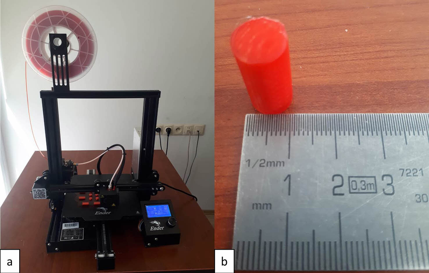
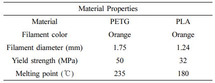
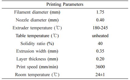
Material and Method. In this experimental study, PLA and PETG filaments supplied from MicroZEY company and material properties of the filaments were shared in Table 1 below. The wear test specimens with diameter of 10 mm and height of 20 mm were designed in Solidworks program and then modelled parts were transferred into 4.3.1 Ultimaker Cura slicing program. In the slicing program, FDM parameters were assigned like tabulated in Table 2 and lastly the g-codes were obtained for the 3D printing process. Lastly, polymer samples were produced with Ender Pro 3 model 3D printer like shown in Figure 1.
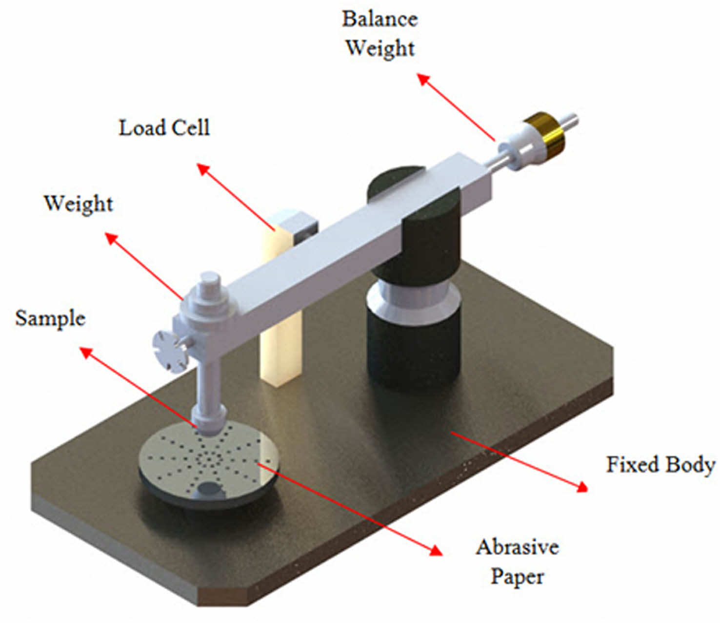
In the abrasive wear test, 5, 10, and 15 N loads were applied to all group samples, and the sliding speeds were determined as 0.5, 1, and 3 m/s, and the sliding distances were determined as 100, 200, and 300 m. 220 mesh abrasive sandpaper was used as abrasive. Abrasive wear tests were performed in a pin-on-disc device (Figure 2), and densities were measured in a RADWAG electrical device. An equal data logger was used in the measurement of wear forces. The experimental setup used in the abrasion tests is given in Figure 2.
The weight losses of the samples were obtained by recording the weights of the samples before and after the wear tests meticulously via Shimadzu ATX-224R precision balance. In addition, the wear test diagrams were characterized using the following equations.
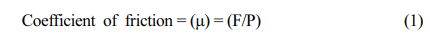
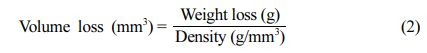
Here F is the friction force measured by the load cell, and P is the normal load applied to the samples. The volume loss was calculated from the following equation using the weight loss and each test was repeated three times.
|
Figure 1 Manufacturing process of the samples: (a) 3D printing process of the samples; (b) 3D printed sample. |
|
Figure 2 Wear test setup (Pin-on disc). |
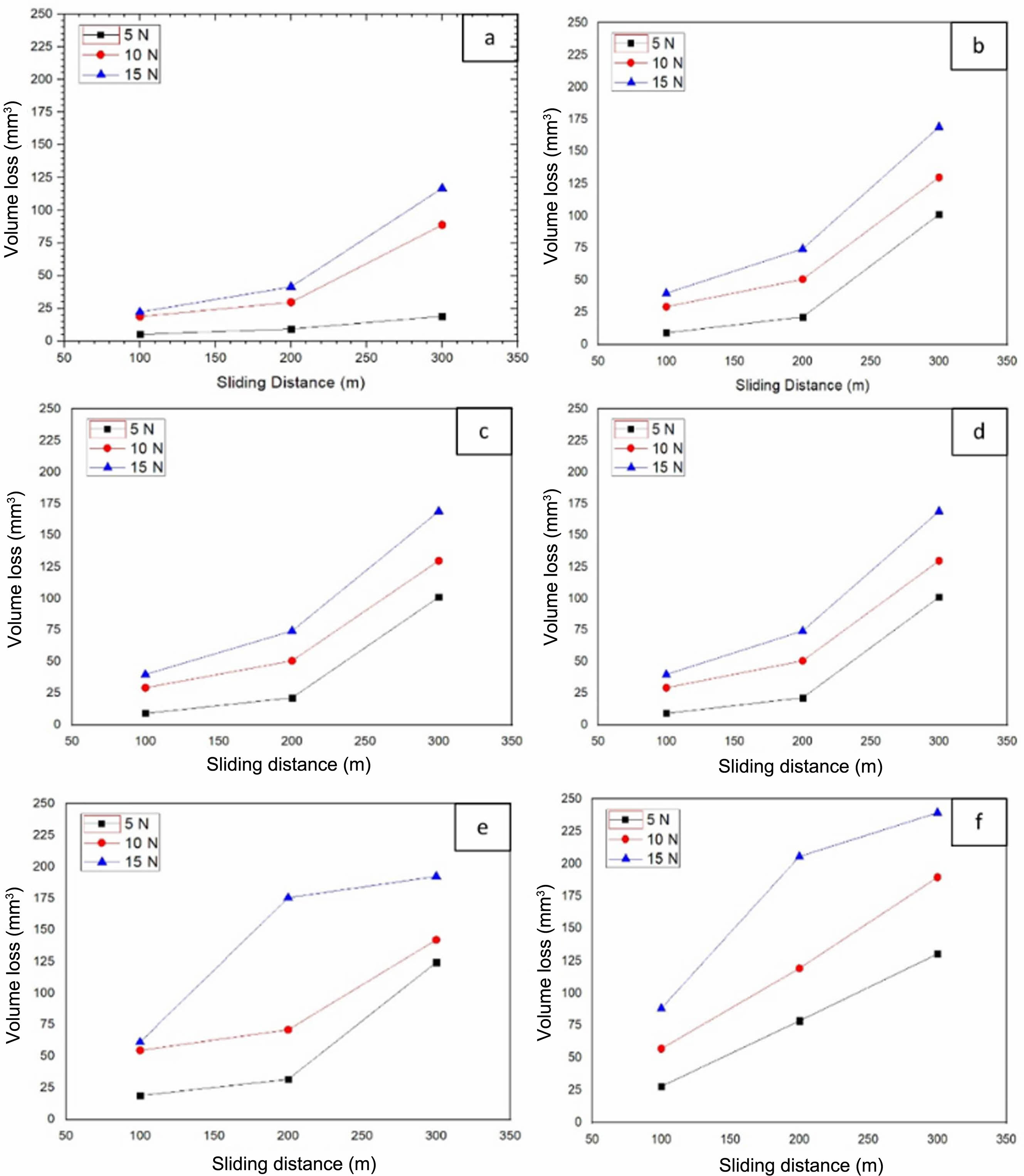
Effect of Wear Conditions on the Volume Loss of PETG and PLA Materials. One of the most important parameters used to characterize wear behavior is volume loss. In order to compare the wear resistance of PETG and PLA materials, the volume loss changes under different wear conditions are examined in Figure 3. Figure 3 clearly shows that the wear resistance of PETG material is better than PLA material and shows less volume loss. A significant increase in volume loss is observed in all samples with increasing sliding distance (Figure 3).
Especially at high sliding distances, significant spikes in volume loss values were observed. This significant change in volume loss can be explained by the increasing temperature and sliding distance at the wear interface.11,13,14 Similar to the sliding distance, the volume loss increases with increasing loads. The highest volume loss was observed in the 300 m sliding distance and 15 N loading sample. Another remarkable point with increasing load is that the differences in volume loss increase significantly at high sliding distances at increasing loads. These sudden fluctuations in volume loss can be attributed to the variable loading conditions occurring at the wear interfaces.10,11,13 In general, when Figure 3 is examined comprehensively, it has been determined that the PETG material has a higher wear resistance (less volume loss), and the weight loss can be optimized using different parameters under different wear conditions. In addition, fluctuations in weight losses can be explained by the load application irregularities that occur during layer changes in samples produced by the additive manufacturing method.
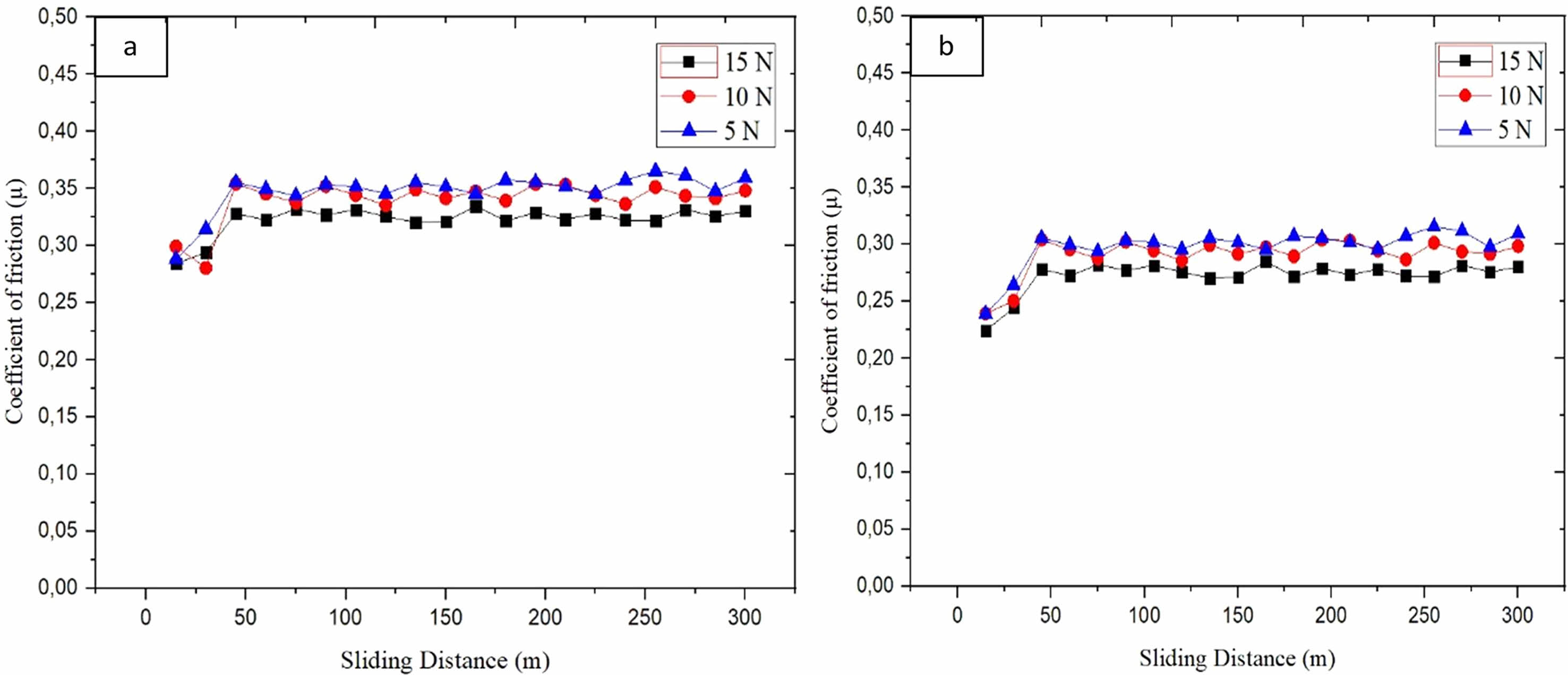
Effect of Wear Conditions on the Friction Coefficient of PETG and PLA Materials. The friction coefficient changes of the samples produced by the additive manufacturing method under different wear conditions, 5, 10, 15 N loading conditions, and 0-300 m sliding distance conditions are given in Figure 4. The friction coefficient changes in PLA samples were investigated (Figure 4). It was observed that PETG samples had a higher coefficient of friction than PLA samples.10-17 When examined in detail in Figure 4, it has been determined that the friction coefficient can be optimized by controlling the wear condition parameters. It was determined that the friction conditions increased significantly with increasing load. This increase in the friction coefficient can be explained by the increase in the wear interface with increasing load, resulting in a decrease in hardness and a significant increase in the amount of wear.11-20 It has been observed that friction forces fluctuate over different sliding distances. These differences in the friction coefficients can be explained by the regular friction forces and the layer changes in the samples produced by the additive manufacturing method.17-20
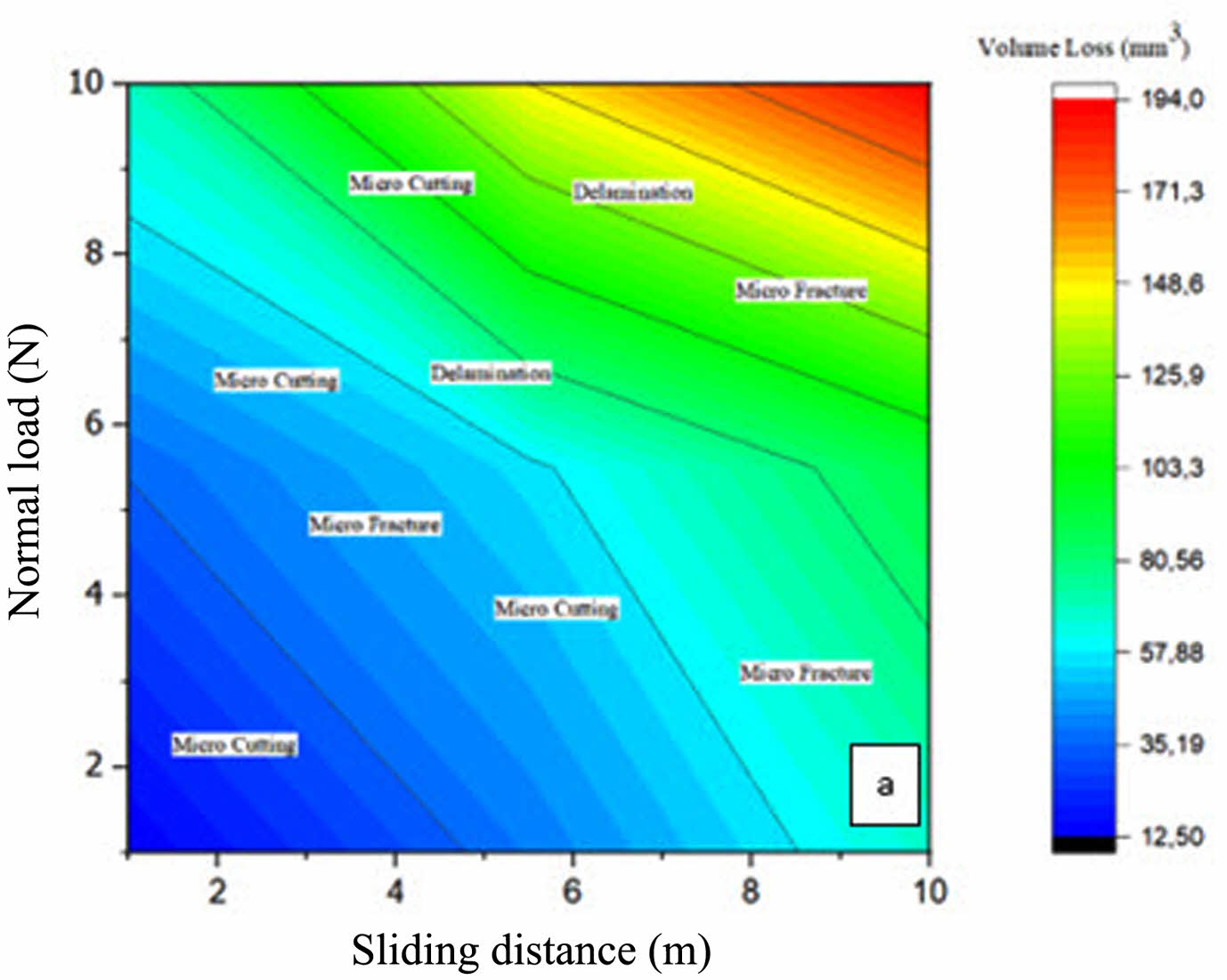
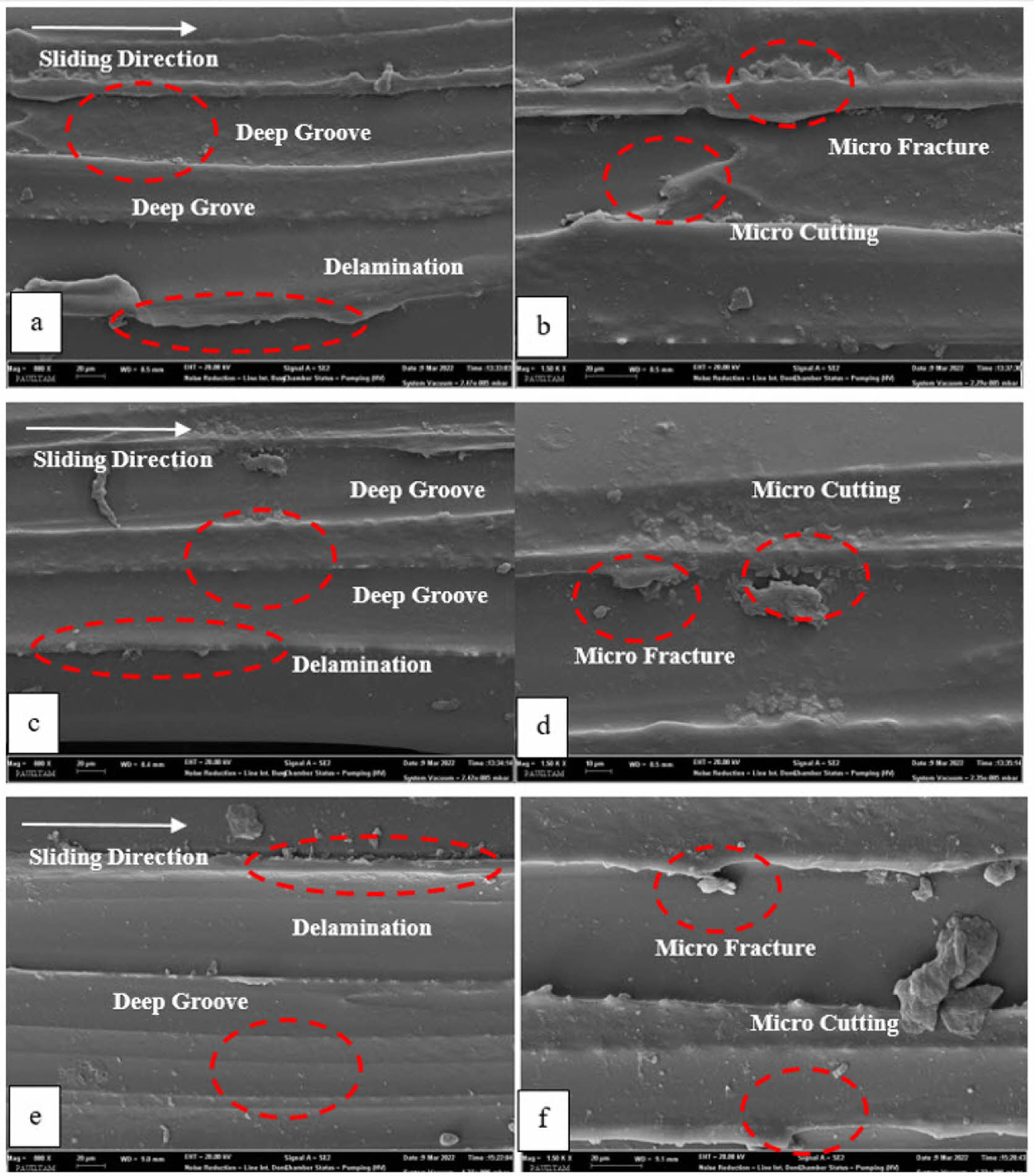
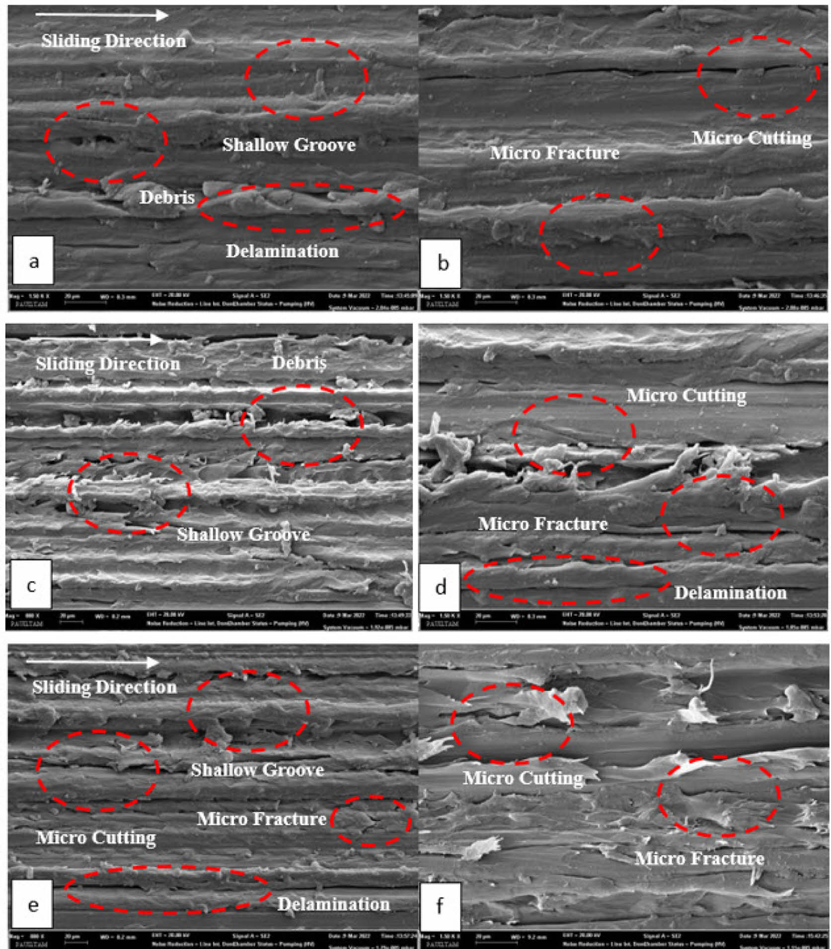
Detection of Wear Mechanisms by Worn Surface Characterization. SEM characterization of the worn surfaces of the worn samples was carried out to determine which wear mechanisms the PETG and PLA samples were exposed to under different wear conditions (Figure 5-6). It was determined that the depth and width of the wear cavities increased significantly with increasing loading conditions with wear cavities formed at low wear loads (Figure 5). In addition, it is observed that debris is formed on the surfaces corresponding to the layer widths of the samples with a layered structure. It has been observed that micro fractures are formed by increasing wear load. Fatigue and micro-cutting wear mechanisms were determined (Figure 5). Wear mechanisms play an essential role in determining and optimizing wear behavior. It is clearly understood in Figure 6 that the wear mechanisms directly determine the wear conditions. At low conditions, it is seen that the micro-cutting mechanism caused by abrasive particles dominates, while the increased sliding distance and delamination and fatigue wear mechanisms seem to be the more dominant mechanisms. Delamination and fatigue mechanisms cause volume loss to increase rapidly. This wear map obtained from the experimental results will form a vital data map for optimizing the wear resistance of the PETG sample under different wear conditions.
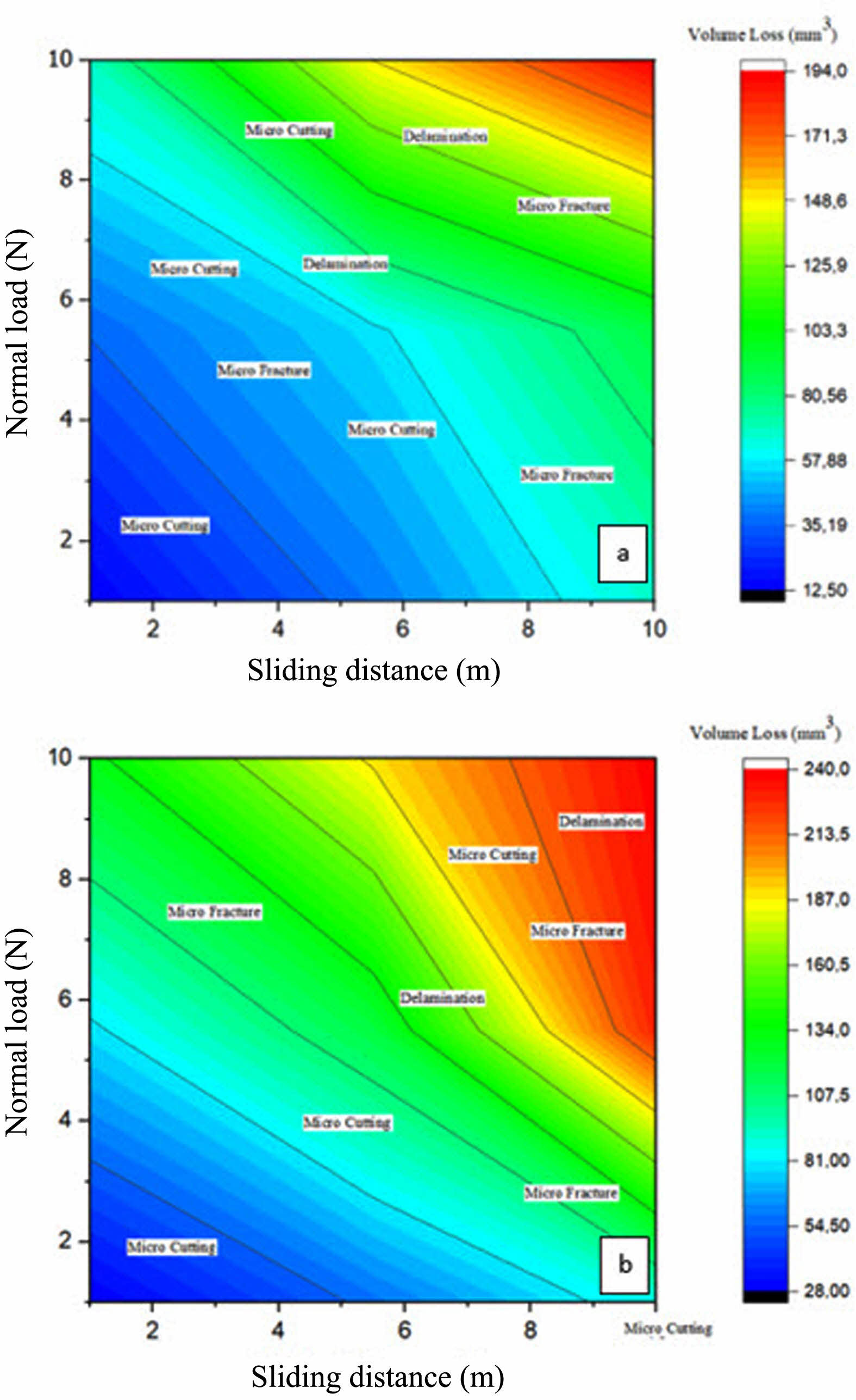
Besides the SEM analyses of worn PLA and PETG parts shared in Figure 5 and Figure 6, the mechanism types were also presented in Figure 7 which demonstrates the change of nominal load against sliding distance.
|
Figure 3 Variation of volume loss with sliding distance as a function of load: (a) PETG-0.5; (b) PETG-1; (c) PETG-3; (d) PLA-0.5; (e) PLA1; (f) PLA-3. |
|
Figure 4 Variation of friction coefficient as a function of sliding distance and load: (a) PETG-3; (b) PLA-3. |
|
Figure 5 SEM Characterization of the worn surfaces of PLA samples: (a) general view of PLA-0.5 surface; (b) detailed view of micro fracture and cutting PLA-0.5; (c) general view of PLA-1; (d) detailed view of micro fracture, cutting and delamination in PLA-1; (e) general view of PLA-3; (f) detailed view of micro fracture and cutting in PLA-3. 600× and 1500× magnification respectively for (a), (c), (e) and (b), (d), (f). |
|
Figure 6 SEM Characterization of the worn surfaces of PETG samples: (a) general view of PETG-0.5 surface; (b) detailed view of micro fracture and cutting PETG-0.5; (c) general view of PETG-1; (d) detailed view of micro fracture, cutting and delamination in PETG-1; (e) general view of PETG-3; (f) detailed view of micro fracture and cutting in PETG-3. 600× and 1500× magnification respectively for (a), (c), (e) and (b), (d), (f). |
|
Figure 7 Wear map of PLA and PETG specimens: (a) PETG-3; (b) PLA-3. |
From this experimental wear study of PETG and PLA parts under different sliding speeds (100, 200, and 300 m) and loads (5, 10, and 15 N), the following major findings were obtained;
• It can be stated that there is a direct relationship between volume loss of PETG and PLA parts with sliding speeds and loads. It can be asserted that increase of temperature with increasing sliding speed and load may play a critical role at this point.
• Coefficient of frictions of the PETG and PLA part were calculated as approximately 0.35 and 0.30 respectively.
• It was determined that the depth and width of the wear cavities increased significantly with increasing loading conditions with were cavities formed at low wear loads.
• As a result of SEM observations, at low conditions, it is seen that the micro-cutting mechanism caused by abrasive particles dominates while the increased sliding distance and delamination and fatigue wear mechanism seem to be the more dominant mechanisms.
- 1. Momber, A. W.; Irmer, M.; Marquardt, T. Effects of Polymer Hardness on the Abrasive Wear Resistance of Thick Organic Offshore Coatings. Prog. Org. Coat. 2020, 146, 105720.
-

- 2. Momber, A. W. Quantitative Performance Assessment of Corrosion Protection Sys-tems for Offshore Wind Power Transmission Platforms. Renew. Energy 2016, 94, 314-327.
-
- 3. Momber, A. W.; Marquardt, T. Protective Coatings for Offshore Wind Energy Devices (OWEAs): a Review, J. Coat. Technol. Res. 2018, 15, 13-40.
-
- 4. Lauer, R. S. Advancements in the Abrasion Resistance of Internal Plastic Coatings. Abu Dhabi, UAE, Mater. Perform 2015, 53, 52-55.
-
- 5. Hosseinpour, D.; Guthrie, J. T.; Berg, J. C. The Effect of α-alumina Filler/acrylic-melamine Polymer Interfacial Interactions on the Abrasion Resistance of An Automotive Topcoat Layer; Elsevier: Prog. Organ. Coat. 2008, 62, 214-218.
-
- 6. Zsidai, L.; Katai, L. Abrasive Wear and Abrasion Testing of PA6 and PEEK Composites in Small-scale Model System. Acta Polytech. Hung. 2016, 13, 197-214.
-
- 7. Benli, M.; Gümüş, B. E.; Kahraman, Y.; Gökçen-Rohlig, B.; Evlioğlu, G.; Huck, O.; Özcan, M. Surface Roughness and Wear Behavior of Occlusal Splint Materials Made of Contemporary and High-performance Polymers. Odontology 2020, 108, 240-250.
-
- 8. Zgalat-Lozynskyy, O. B.; Matviichuk, O. O.; Tolochyn, O. I.; Ievdokymova, O. V.; Zgalat-Lozynska, N. O.; Zakiev, V. I. Polymer Materials Reinforced with Silicon Nitride Particles for 3D Printing. Powder Metall. Met. Ceram. 2021, 59, 515-527.
-
- 9. Franco, M. F.; Gadioli, R.; Paoli, M. A. Presence of Iron in Polymers Extruded with Corrosive Contaminants or Abrasive Fillers. Polimeros-Ciencia e Tecnologia 2019, 29, 2.
-
- 10. Yavuz, G. A.; Gören Kıral, B.; Katre, S.; Atilla, D. Effects of Topology and Material on Mechanical Properties of Structures Produced by the Additive Manufacturing Method. Dokuz Eylul University Faculty of Engineering Science and Engineering Journal. 2021, 23, 755-765.
-
- 11. Abeykoon, C.; Sri-Amphorn, P.; Fernando, A. Optimization of Fused Deposition Modeling Parameters for Improved PLA and ABS 3D Printed Structures. Int. J. Lightweight Mater. Manuf. 2020, 3, 284-297.
-
- 12. Ergene, B.; Yalçın, B. Investigation on Mechanical Performances of Various Cellular Structures Produced with Fused Deposition Modeling (FDM). J. Fac. Eng. Archit. Gazi Univ. 2023, 38, 201-217.
-
- 13. Rajesh, J.; Bijwe, J.; Tewari, U. S. Abrasive Wear Performance of Various Polyamides. Wear 2002, 252, 769-776.
-
- 14. Rajesh, J.; Bijwe, J.; Tewari, U. S. Influence of Fillers on Abrasive Wear of Short Glass Fibre Reinforced Polyamide Composites. J. Mater. Sci. 2001, 36, 351-356.
-
- 15. Kumara, S.; Panneerselvam, K. Two-Body Abrasive Wear Behavior of Nylon 6 and Glass Fiber Reinforced (GFR) Nylon 6 Composite. Procedia Technol. 2016, 25, 1129-1136.
-
- 16. Patnaik, A.; Satapathy, A.; Chand, N.; Barkoulad, N. M.; Biswasb, S. Solid Particle Erosion Wear Characteristics of Fiber and Particulate Filled Polymer Composites: A Review. Wear 2010, 268, 249-263.
-
- 17. Harsha, A. P. An Investigation on Low Stress Abrasive Wear Characteristics of High Performance Engineering Thermoplastic Polymers. Wear 2011, 271, 942-951.
-
- 18. Tervoort, T. A.; Visjager, J.; Smith, P. On Abrasive Wear of Polyethylene. Macromolecules 2002, 35, 8467-8471.
-
- 19. Guptaa, M. K.; Srivastava, R. K.; Bisaria, H. Potential of Jute Fibre Reinforced Polymer Composites: A Review. Int. J. Fiber Text. Res. 2015, 5, 30-38.
- 20. Mahapatra, L.; Mohanty, S. The Effect of Strain Rate on Jute Fibre Composites; National Institute of Technology: Rourkela, 2007.
- Polymer(Korea) 폴리머
- Frequency : Bimonthly(odd)
ISSN 0379-153X(Print)
ISSN 2234-8077(Online)
Abbr. Polym. Korea - 2023 Impact Factor : 0.4
- Indexed in SCIE
 This Article
-
2023; 47(3): 257-263
Published online May 25, 2023
- 10.7317/pk.2023.47.3.257
- Received on Apr 27, 2022
- Revised on Feb 16, 2023
- Accepted on Mar 14, 2023
Services
- Full Text PDF
- Abstract
- ToC
- Acknowledgements
- Conflict of Interest
Introduction
Experimental
Results and Discussion
Conclusions
- References
Shared
Correspondence to
- Gökmen Atlıhan†
-
Department of Mechanical and Manufacturing, Pamukkale University, 20400, Turkey
- E-mail: gatlihan@pau.edu.tr
- ORCID:
0000-0002-3476-686X
Hyecheon Building(Room 601), #354, Gangnam-Daero, Gangnam-Gu, Seoul 06242, Korea
TEL : 82-2-568-3860, 561-5203, 569-3860 FAX : 82-2553-6938 E-mail: polymer@polymer.or.kr