


- Fabrication of Various Cellulose Microstructures via Oil-templated Regeneration of Cellulose Within a Simple Microfluidic System
Na Rae Lee# , Seungdeok Seo# , In Hyeok Oh, and Suk Tai Chang†

School of Chemical Engineering and Materials Science, Chung-Ang University, 84 Heukseok-ro, Dongjak-gu, Seoul 06974, Korea
- 단일 미세유체장치를 이용한 셀룰로오스 재생을 통한 다양한 셀룰로오스 미세구조 제작
이나래# · 서승덕# · 오인혁 · 장석태†
중앙대학교 화학신소재공학부
Reproduction, stored in a retrieval system, or transmitted in any form of any part of this publication is permitted only by written permission from the Polymer Society of Korea.
This paper proposes a novel method for fabricating oil-phase-containing cellulose microfibers, microtubes, and microcapsules using a one-step continuous process in a single microfluidic system. The proposed method is based on the regeneration of cellulose, that is, when an ionic liquid (IL) is dissolved in antisolvents of cellulose such as water, the cellulose dissolved in the IL is aggregates and regenerates on the surface of mineral oil present in the system to form a cellulose microstructure. By controlling the flowrate of each fluid, various cellulose microstructures containing mineral oil can be formed. Notably, the cellulose microstructures produced using this approach remains stable even after one year. This method can also be applied to form cellulose microfibers containing polystyrene beads and hollow cellulose microcapsules. Therefore, it is anticipated that the proposed method for the preparation of cellulose particles and core-shell structures has significant potential in medicine delivery, cosmetics, and electronic materials.
본 논문은 단일 미세유체 시스템에서 1단계 연속 공정을 사용하여 유상 함유 셀룰로오스 미세섬유, 마이크로튜브 및 마이크로캡슐을 제조하는 새로운 방법을 개발하였다. 제안된 방식은 셀룰로오스의 재생을 기반으로 하며, 이는 이온성 액체를 물과 같은 셀룰로오스의 반용매에 용해시키면 용해된 셀룰로오스가 미네랄 오일 표면에 응집되어 셀룰로오스 미세구조를 형성하는 방식이다. 특히, 간단하게 유체의 유량을 조절하는 것만으로 미네랄 오일을 함유한 다양한 셀룰로오스 미세구조를 형성할 수 있다. 이 접근법으로 생산된 셀룰로오스 미세구조는 1년 후에도 안정적으로 유지됨을 확인하였다. 또한, 마이크로 고분자비드를 포함하는 속이 빈 셀룰로오스 마이크로캡슐과 마이크로섬유를 형성하는 데에도 적용될 수 있다. 본 연구에서 제안한 셀룰로오스 재생 기반의 제작 방식은 의약품 전달, 화장품 및 전자 재료 분야에서 상당한 잠재력을 가질 것으로 기대된다.
A single process for fabricating varied cellulose microstructures is developed in a single microfluidic system. The characteristics of the microcellulose can be determined by simply varying the flow rate of each flow.
Keywords: cellulose, microfluidic system, ionic liquids, microcapsules, microfibers, microtubes.
This research was supported by a National Research Foundation of Korea (NRF) grant funded by the Korean government (MSIT) (No. 2022R1A2C1005739), the H2KOREA funded by the Ministry of Education (2022Hydrogen fuel cell-003, Innovative Human Resources Development Project for Hydrogen Fuel Cells), and a Chung-Ang University Graduate Research Scholarship in 2022.
The authors declare that they have no known competing financial interests or personal relationships that could have appeared to influence the work reported in this paper.
Information is available regarding the optical microscope images of the generation of the various cellulose microstructures, the demonstration of micromaterials retention, and characterization. Supplementary date to this article can be found online at http://journal.polymer-korea.or.kr.
PK_2024_048_02_242_Supporting_Information.pdf (764 kb)
Supplementary Information
Cellulose is a natural polymer and an eco-friendly alternative to petroleum-based products; it is abundant, renewable, biodegradable, and biocompatible, making it of significant interest for applications in industries such as paper, textiles, and healthcare.1-4 However, with a molecular formula of C6H10O5 and a polysaccharide structure composed of β-1,4-D-glucose units, cellulose is highly stable owing to intra- and inter-chain hydrogen bonding networks, making it insoluble in water and conventional organic solvents.1-6 The insolubility of cellulose in conventional solvents, as well as the strong intermolecular and intramolecular hydrogen bonds, pose significant challenges during its chemical processing.
To solve these challenges, a viscose process to produce cellulose fibers and derivatives and a N-methylmorpholine-N-oxide (NMMO) solution process for cellulose regeneration from the solvent have been developed.3,5,7 However, the viscose process is functionally challenging, requires the highest quality dissolving pulp, and is environmentally harmful owing to the use of harmful chemicals (CS2, H2S, and heavy metals). Compared to the viscose process, the NMMO method has the advantage of being eco-friendly; however, it also has disadvantages, including high financial investment, challenging solvent recovery, and limited flexibility for modifying and varying properties.8
Ionic liquids (ILs) are promising eco-solvents that are recyclable as well as chemically and thermally stable because of their negligible vapor pressure and high solubility, and they are effective solvents for dissolving cellulose and other natural polymers.9-12 Underivatized solvents break the intramolecular hydrogen-bond network in cellulose, resulting in its solubilization as new hydrogen bonds form between the hydroxyl protons and anions of the IL.3 The cellulosic materials dissolved in the IL are then regenerated by coagulation by adding antisolvents—solvents in which the cellulose is less soluble—such as water or alcohols; this also results in efficient recovery of the IL. Regenerated cellulose can be utilized for biofuels and other bioproducts, and its applications have shown remarkable potential.
Microfluidic systems are being employed frequently in a variety of analytical and chemical processes to produce microsized emulsion distributions, fiber structures, and so on, as the size, shape, and composition of the produced particles can be controlled.13,14 Examples of such particles include homogenous microspheres,14-16 janus microparticles,15,17 hollow microspheres,18,19 and hollow microcapsules,20,21 as well as structures such as microfibers,22-25 and microtubes.25 Furthermore, microfluidic systems allow for continuous, repeatable, and scalable production. In particular, advanced technology for fabricating microfibers and microcapsules using microfluidic-based techniques (e.g., the use of different coagulation methods, platforms, geometries, and biomaterials) is being utilized in new fiber application fields by introducing various processes without complicated devices or facilities. However, developing a microchannel structure is challenging; for instance, multiple steps are required to prepare various channels to achieve the desired outcome. Additionally, it is challenging to precisely and simultaneously control the amount of a multiphase fluid because the flowrate, which regulates the volume of the microfluid in the microchannel, is highly unstable in the external environment and requires modification depending on the fluid.26,27
Herein, we report a novel and facile approach for producing cellulose microstructures with embedded mineral oil in a flow-focusing microchannel with Y-junctions. The single-step continuous process can fabricate various microscale hybrid architectures of cellulose, such as fibers, short threads, tubes, and capsules, within a single microfluidic device. The production of these cellulose microstructures is based on the regeneration of cellulose from an IL, 1-ethyl-3-methylimidazoluin acetate (EMIM-Ac), on the surface of oil templates in a microchannel. Mineral oil, cellulose in EMIM-Ac, and glycerol-containing water were independently injected into the input, middle, and output channels to create oil–cellulose microstructures. In the first channel, mineral oil was embedded in the cellulose solution, following which the cellulose solution containing EMIM-Ac was exposed to water containing glycerol. Diffusion at the IL–water interface then caused the cellulose to regenerate.
We focused on the fabrication of cellulose microstructures with various morphologies utilizing the regeneration of cellulose in a single device, as opposed to the generally independent fiberization and encapsulation processes that are conducted in a single microfluidic system. Both the morphology and size of the oil particles embedded in the cellulose were controlled by varying the flowrates of the mineral oil, cellulose solution, and glycerol-containing water. The proposed method offers the following advantages: 1) fabrication of eco-friendly microstructured materials based on regenerated cellulose; 2) production of cellulose microstructures with various morphologies and sizes from simple fluid flowrate control; and 3) a variety of delivery carriers, including with polymers and functional additives, can be produced without material constraints. Our method has the potential to produce and synthesize hybrid microstructures of various shapes and sizes. We believe that this novel process is simple, effective, and eco-friendly compared with previous studies for processing cellulose into microstructures.
Fabrication of Microfluidic Device. The microfluidic device was fabricated in poly(dimethylsiloxane) (PDMS) (Sylgard 184, Dow Corning, USA) using a soft lithography procedure. Briefly, SU-8 2050 photoresist (MicroChem, Inc., Japan) was coated on a silicon wafer using a spin-coater (ACE-200, Spin Coater, Korea). After soft-baking, a film photomask containing a microchannel printout was placed on the SU-8 photoresist, followed by UV exposure (UVCURE-60PH, Lichtzen, Korea). The channel master was developed using SU-8 developer solution (MicroChem, Inc., Japan). The PDMS precursor was then cast onto the SU-8 channel master and cured at 70 ℃ for 6 h. The PDMS slab containing the microchannel structure was then irreversibly sealed on a glass slide after an air plasma treatment (PDC-32G, Harrick Plasma, New York, USA). The length of the microchannel was 80 μm. The widths of the channels for injecting oil, cellulose–ionic liquid, 1-ethyl-3-methylimidazolium acetate (EMIM-Ac) (Sigma-Aldrich, USA), and the aqueous phase were 30, 50, and 50 μm, respectively. The dimension of the oil-template and output channels were 100 μm × 2 mm (width × length) and 100 μm × 3 mm (width × length), respectively.
Fabrication of Oil-templated Cellulose Microstructures. Cellulose powder (Sigma-Aldrich) was completely dissolved in EMIM-Ac at 100 ℃ for 3 h to obtain cellulose solutions with concentrations of 1.5 and 2.0 wt%. Mineral oil and toluene were purchased from Sigma-Aldrich and used as the oil phase flow without the addition of surfactants. The cellulose solution and mineral oil contained 10-4 M Sudan I and 10-4 M Oil Blue N fluorescent dyes, respectively, to characterize the oil core and cellulose shell, respectively, in the cellulose microstructures. Polystyrene (PS) (Mw~350000 g/mol and Mn~170000 g/mol, Sigma-Aldrich) was dissolved in toluene at a concentration of 10 mg mL–1 to incorporation of PS beads within the cellulose fibers. An aqueous sheath flow (40 v/v% glycerin in deionized water) was introduced at the output channel to regenerate the cellulose. Each flow was injected into the microfluidic device using a syringe pump (LEGATO 101, KD Scientific Inc., USA).
Characterization. Optical microscopy images of the flow in the microchannel were acquired using a Nikon TS100-F (Japan) inverted microscope. An Olympus BX-51 microscope and a high-resolution ProRes CF Scan digital CCD camera (Jenoptik, German) were used to obtain bright-field and fluorescent images of the various cellulose microstructures produced by the microfluidic device. The scanning electron microscopy (SEM) images of the cellulose capsules and the PS-hybridized cellulose fibers were obtained using a Carl Zeiss SIGMA FE-SEM (German).
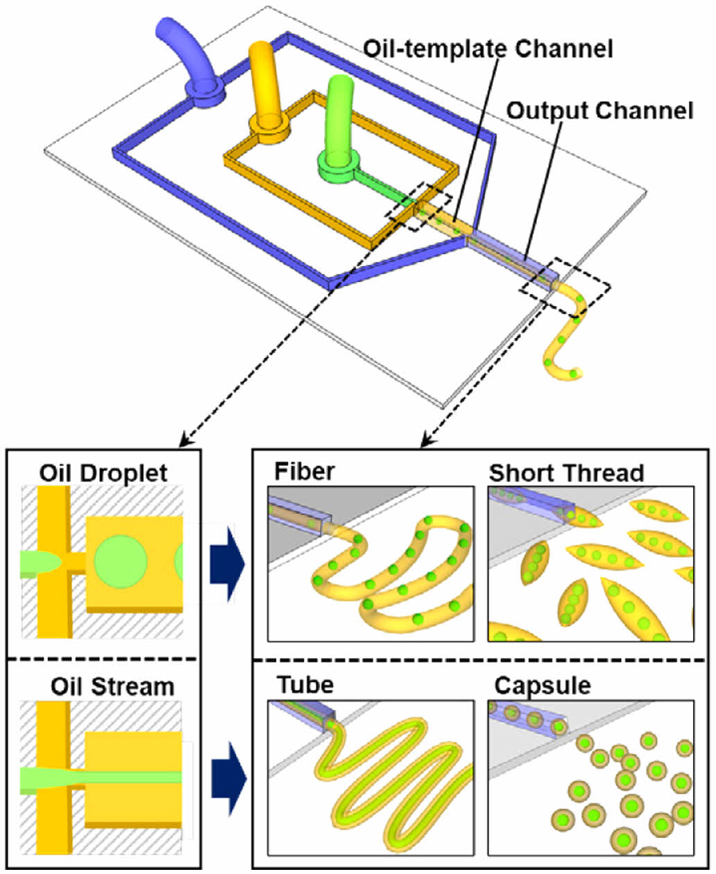
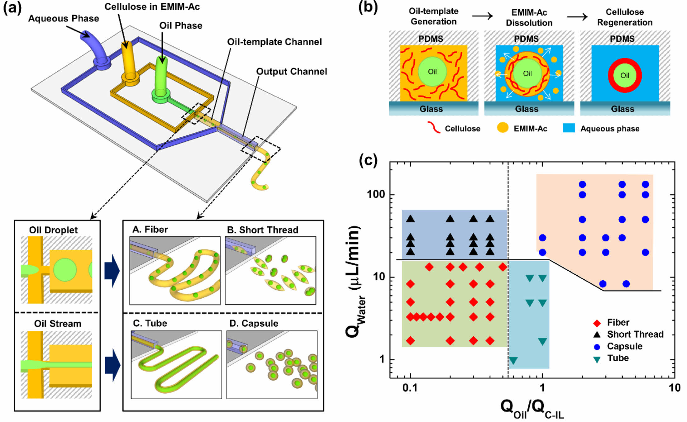
A novel microfluidic system was developed for the formation of capsules and fibers of various morphologies and sizes without using advanced equipment or facilities. Figure 1 shows the design of the proposed fabrication process for various cellulose microstructures and the principle of cellulose regeneration on the oil-templates. Schematics of the microfluidic device and various oil-templated cellulose microstructures are presented in Figure 1(a). The cellulose microstructures produced by the fabricated microfluidic device exhibited tunable morphological and structural features owing to the oil- and aqueous-phase flowrates; that is, varying the flowrates of the fluids in the microfluidic system allowed variable control of the chemical and morphological properties of cellulose at the micrometer scale.
Figure 1(b) shows the principle of the regeneration of cellulose dissolved in EMIM-Ac into an oil–cellulose core–shell structure. The cellulose–ionic liquid (C-IL) solution was merged with the oil flow, resulting in its transportation to the oil–template channel junction, followed by subsequent decomposition in the output channel upon mixing with an aqueous flow containing glycerin. In general, mixing the solvent with an antisolvent is a good process for obtaining crystals, particularly of organic compounds. When the water and glycerin solution, both of which are antisolvents for cellulose, was added to the C-IL solution, hydrogen bonds formed between H2O, the hydroxyl groups in cellulose, and the oxygen atoms in acetate28,29; the number of hydrogen bonds between cellulose molecules is closely related to the solubility of cellulose. In a previous study, we proposed that the concentration of glycerin affects the size of the fibers and that an increase in the viscosity of an aqueous fluid causes the size of the microfibers to decrease. The mixture of water and glycerin was therefore employed to control the morphology and size of the different cellulose microstructures.
We observed the cellulose microstructures produced upon controlling the rate of each flow. Hereinafter, QW, QOil, and QC-IL refer to the flowrates of the aqueous phase, mineral oil, and C-IL solution, respectively. The phase diagram in Figure 1(c) shows the various cellulose microstructures produced at different flowrates of each fluid. When the flowrate ratio of the merged fluid (QOil/QC-IL) was low, oil droplets were formed in the oil-template channel and the oil-droplets embedded microfibers or short threads were produced depending on the QW. Meanwhile, when QOil/QC-IL was increased, the oil phase flew in the form of a stream and the cellulose microtubes or capsules were produced. Therefore, using this system, various morphologies and sizes of cellulose microstructures can be fabricated by simply changing the fluid flowrates during cellulose regeneration.
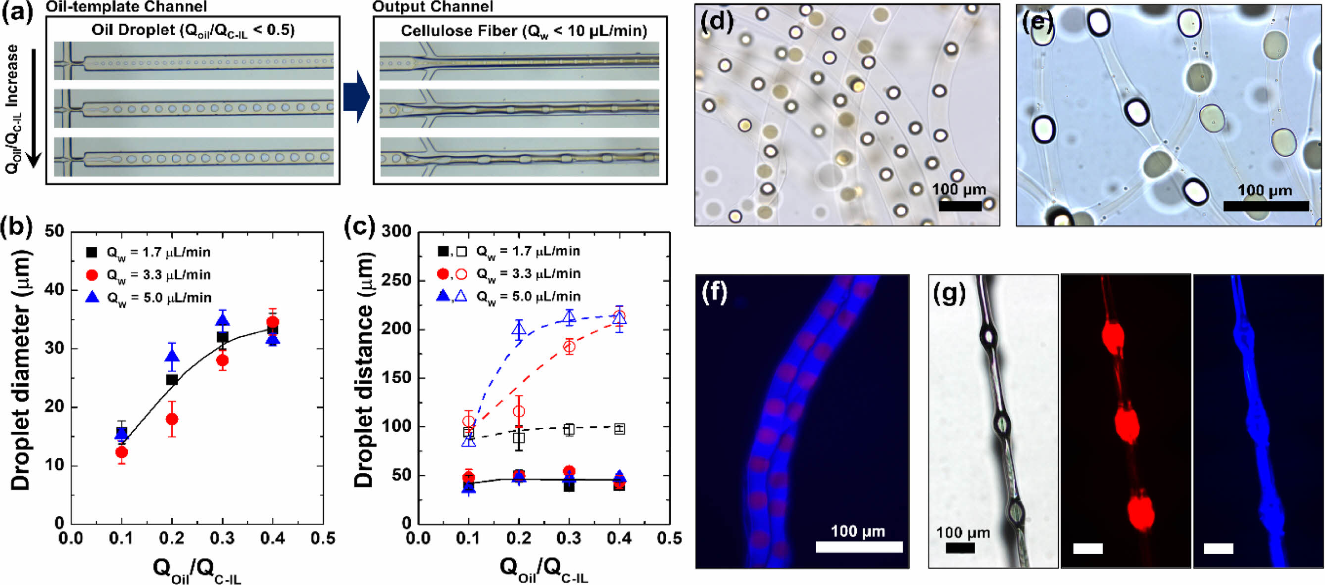
The flow patterns inside and at the exit of the capillary were observed using an optical microscope. Cellulose regeneration occurred when the IL was dissolved in the aqueous phase (sheath flow) in the output channel, which caused the cellulose in the IL to be regenerated and simultaneously aggregated onto the oil droplets. Optical microscopy observation of the cellulose microstructures removed from the aqueous solution immediately after formation revealed that oil droplets were embedded at regular intervals within the contracted cellulose fibers (Figure 2). These oil droplets served as the cores of knots; thus, knot-shaped cellulose fibers could be produced using the simple microfluidic technique. As the microdroplets flowed out according to the difference between the flowrate of the merged flow generated in the oil-template channel (core flow) and the flowrate of the sheath flow in the output channel, dissolution of the IL and coagulation of cellulose occurred simultaneously during the production process. Figure 2 shows the main results and characteristics of the core–sheath flow interactions (QOil/QC-IL < 0.5). To fabricate microfibers, we varied the QOil in the range 0.1 to 0.4 μL min–1 and the QW between 1.7, 3.3, and 5.0 μL min–1 at a fixed QC-IL of 1.0 μL min–1.
When the QW was fixed at 5.0 μL min–1 and the QOil was varied between 0.1, 0.2, and 0.3 μL min–1, cellulose fibers orderly embedded with oil droplets were formed (Figure 2(a)). As shown in Figure 2, changing the flowrate of each flow affected the knot-shaped cellulose fibers. It has been reported that the flowrate ratio of the core flow to the continuous sheath flow can significantly affect the diameters of the microdroplets.30,31 In our study, oil droplets with diameters of 36, 56, and 69.2 μm were formed at QOil values of 0.1, 0.2, and 0.3 μL, respectively (Figure 2(a)), showing that the oil droplet diameter increased with increasing oil flowrate. The final distance between the oil droplets was then determined using QW and the oil droplet size (which depended on QOil/QC-IL).
To determine which factor had a greater influence on the morphology and size of the knot-shaped cellulose fibers, the effects of changing the core and sheath flows were observed. As the QOil/QC-IL ratio increased, the size of the oil droplets also increased (Figure 2(b)). At QOil = 0.3 μL min–1 and QC-IL = 1.0 μL min–1, the intervals between the oil droplets embedded in the cellulose fiber were 97, 182.5, and 212.4 μm at QW values of 1.7, 3.3, and 5.0 μL min–1, respectively (Figure 2(c)). The distance between the droplets was then determined according to their size by varying QOil between 0.1, 0.2, and 0.3 μL min–1 at QC-IL = 1.0 μL min–1 and QW = 3.3 μL min–1 (Figure S1). Thus, our method allows the length, width, and diameter of the microfibers, as well as the distance between the knots, to be conveniently controlled by simply varying the flowrate of each fluid.
The dynamics of droplet deformation and restriction in accelerating flow are responsible for the formation of microfiber knots.30,32-34 In this study, the main factors affecting the knot spacing and oil droplet size were the QW and flowrate ratio of the core flow, respectively. The spacing between knots can be estimated using the following equation of L = VW/p(DM/2)2,34 where L, VW, and DM are the knot spacing, aqueous solution volume, and microchannel diameter, respectively. In a microfluidic system with fixed capillary dimensions, the distance between droplets is proportional to the flowrate of the aqueous solution. Therefore, the QW-dependent intervals can be indicated as a linear response from the moment when the size of the oil droplet causes the formation a knot shape (e.g., L = 34.76 μm at VW = 48.1 μL, QOil/QC-IL = 0.2, and QW = 5.0 μL min–1). Because the fiber diameter is constrained by the fixed dimensions of the microchannel, the distance between the droplets appears to converge at a certain point. Figures 2(d, e) show that at a QOil/QC-IL and QW of 0.3 and 5.0 μL min–1, respectively, the production of a large droplet (69.2 μm) formed a distinct knot structure; meanwhile, at a lower QOil/QC-IL and QW of 0.1 and 1.7 μL min–1, respectively, the droplet was unable to form a knot in the cellulose microfiber structure. Therefore, it was apparent that a knot could only be formed when the size of the oil droplet approached the diameter of the fiber, which in turn was determined by the size of the microchannel. The cellulose fibers containing the prepared mineral oil droplets were confirmed to be dry. Figure 2(f) shows a fluorescence image of the dried cellulose fiber structure formed at QOil = 0.2 μL min–1, QC-IL = 1.0 μL min–1, and QW = 1.7 μL min–1. Figure 2(g) shows the structural information of the knot-shaped cellulose fiber formed at QOil = 0.2 μL min–1, QC-IL = 1.0 μL min–1, and QW = 5.0 μL min–1.
When the QW was increased (> 10 μL min–1), the cellulose microstructure was produced in the form of short threads (Figure 1(c) and Figure S2), owing to the cellulose fibers breaking. Figure S2(a) shows the differences between the short fiber lengths and oil droplet intervals when the QW was varied between 15, 30, and 50 μL min–1 at a constant QOil/QC-IL of 0.1. Figures S2(b–d) show the different sizes of the droplets contained in the same volume of the threads at the same QW of 30 μL min–1 when the QOil/QC-IL was varied between 0.1, 0.3, and 0.4. The results show that while continuous fibers cannot be produced, short cellulose threads that enclose microdroplets of a specific size at regular intervals can be produced.
Knot-shaped microfibers have been fabricated by electrospinning,35 dip coating,36 and microfluidic systems37; however, these methods offer limited control over the microstructural features of the fibers, such as the size of the knots and the distance between them. The novelty of the fabrication process developed in this study lies in the ability to control the fiber properties by simply varying the rate of each flow. This approach allows good microscale droplet controllability, enabling the production of microfibers with precisely controlled knot structures. Microfibers with unique periodic knot structures can thus be fabricated and employed in applications such as spiderweb networks in tissue engineering, water collection,38,39 and chemical delivery.40
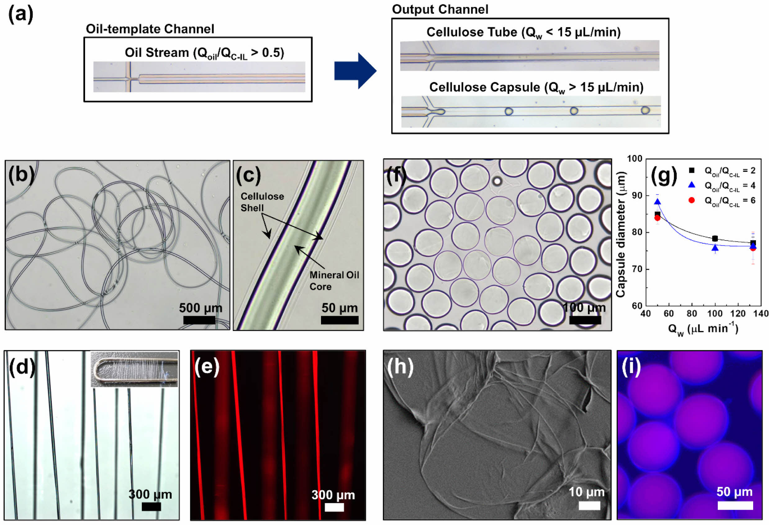
When the QOil/QC-IL exceeded 0.5, the core flow was a mineral oil stream flowing parallel to the cellulose solution with a consistent flow output through the oil-template channel (Figure 3(a)). This was because the relatively high flowrate of the mineral oil caused laminar flow occurs under interfacial tension, resulting in the formation of an oil stream. The mineral oil core stream, which had a diameter of 50 µm, was then covered by a cellulose shell to form a microtube structure. The cellulose tubes produced were dispersed in water and observed using bright-field microscopy (Figure 3(b, c)). When the QW was relatively low (< 15 μL min–1), the cellulose was regenerated on the surface of the oil stream to form a tube shell while the oil stream was preserved.
It was observed that the width of the mineral oil stream increased with increasing oil flowrate. This is the same reason why the oil droplets became larger with increasing oil flowrate when fabricating cellulose fibers (Figure S3). In this study, the width of the stream was controlled by manipulating the QOil/QC-IL. The cellulose microtube diameter could also be controlled by changing the concentration of the cellulose solution or glycerin in the aqueous solution. We previously reported that the dimensions of cellulose microfibers are determined by changes in both the flowrate and fluid viscosity in the aqueous phase.41 The effect of the shear stress (τ) under aqueous flow on the dimensions of the cellulose tubes can be estimated according to the following approximate proportional equation of t = μQ/h2w,30,41 where m is the fluid viscosity, Q is the flowrate, and h is the height, and w is width of the output channel, respectively. Thus, the dimension of the cellulose tube could be controllable by changing the flowrate and viscosity. However, for the tube structure to function constantly, the flowrate of the sheath flow needs to be slow and steady because the aqueous-phase fluid, which contains 40 vol.% of glycerin, influences the hydrodynamic instability of the produced cellulose structures.
The cellulose tubes containing the mineral oil stream were dried as shown in Figures 3(d, e). Figure S4 shows the structural information of the cellulose tubes, which agrees with the explanation of the homogeneous cellulose tubes being produced while a continuous oil stream was preserved. In our method, simply varying the fluid flowrate within a single microchannel allows continuous and reproducible production with precise control of the microtube form, making it highly advantageous compared to conventional microfluidic synthesis of microfibers.
Cellulose capsules could also be prepared by increasing the QW to above 15 μL min–1 (Figure 3(a)) and ensuring a slightly higher QOil than QC-IL, that is, QOil/QC-IL > 1. Furthermore, the QW needed to be sufficiently high to break up the merged stream and produce capsules. The formation mechanism of homogenous cellulose capsules was similar to that of oil droplets produced in the form of short threads at a relatively higher QW. Removal and observation of the cellulose structures immediately after formation revealed that microcapsules of the same size were produced at regular and periodic intervals. For example, at QOil = 1.0 μL min–1, QC-IL = 0.5 μL min–1, and QW = 100 μL min–1, microcapsules with a diameter of 78.3 μm were regularly formed (Figure 3(f)).
At a fixed QC-IL of 0.5 µL min–1, QOil was varied between 1.0, 2.0, and 3.0 μL min–1 and QW was varied between 50.0, 100, and 133.4 μL min–1. The results confirmed that the size of the cellulose capsules could be controlled by varying the internal oil and aqueous phase flowrates (Figure 3(g)); furthermore, it implied that the morphologies and sizes of the cellulose microstructures could be controlled even at high flowrates. When the QOil and QC-IL were fixed at 1.0 and 0.5 μL min–1, respectively, varying the QW between 50.0, 100.0, and 133.4 μL min–1 resulted in cellulose microcapsule diameters of 85.0, 78.3, and 77.2 μm, respectively. This implies that the size of the cellulose capsule containing the mineral oil was determined by the aqueous-phase flowrate; the faster the QW, the smaller the size of the cellulose microcapsules. Figures 3(h, i) show SEM images of the oil–cellulose microcapsules with core–shell structures. The produced cellulose capsules were stable when maintained in water for 1 year (Figure S5), proving the high retention of the micromaterials from the approach in the present study. Figures 3(h) and S6 show the traces of oil embedded in a thin cellulose shell.
Cellulose microcapsules are drawing significant interest in the applications owing to the controllability of the particle size and distribution as well as the shape and high surface area of the particle surface.14-19,21 During drug delivery, microcapsules protect against unstable chemicals and release the core material into a specific environment (e.g., specific pH and temperature). In our method, cellulose was regenerated by utilizing the interaction between an IL and cellulose in an antisolvent to produce microcapsules with an oil core and cellulose shell through decomposition-induced phase separation in the aqueous phase. This method results in precise control of the size of the cellulose capsules, allowing them to form eco-friendly shells for robust microcapsules. To form hollow microcapsules using our method, we used a volatile solvent for the core stream instead of mineral oil (Figure 4(a)); evaporation of the solvent inside the fabricated microcapsules resulted in cavities. Bright-field microscopy observation confirmed the production of cellulose shells with toluene cores and the subsequent formation of cavities after 20 min owing to complete evaporation of the toluene (Figure 4(c)). The hollow cellulose shells had diameters of 80 µm and were homogeneous in size and shape (Figures 4(d, e)). This simple flow-rate-dependent method allows the eco-friendly fabrication of hollow cellulose capsules by simply changing the flowrate of the microfluid without the use of complicated devices or facilities.
We also injected toluene containing the PS in the form of droplets into an oil-template channel to produce cellulose fibers. As the toluene evaporated, the PS beads were formed, resulting in the synthesis of cellulose fibers embedded with PS particles, as illustrated in Figure 4(b). The cellulose microfibers orderly embedded with PS particles were also observed in water (Figure 4(f)), similar to the morphology of oil droplets embedded in cellulose microfibers. The cellulose fiber embedded with PS beads was synthesized using solutions of 2 wt% cellulose in EMIM-Ac and 10 mg mL–1 PS in toluene at QOil/QC-IL = 0.4 and QW = 10 μL min–1, which were the production conditions for knot-shaped microfibers. Figures 4(g, h) showthat PS bead-hybridized cellulose fibers were successfully produced with a knotted morphology, depending on the flowrates of the fluids. The structure of the PS beads embedded in the cellulose fiber was confirmed (Figure 4(i)), and it was demonstrated that the proposed microfluidic device in the present study can homogeneously produce various hybrid cellulose microstructures simply by changing the flowrates of the fluids.
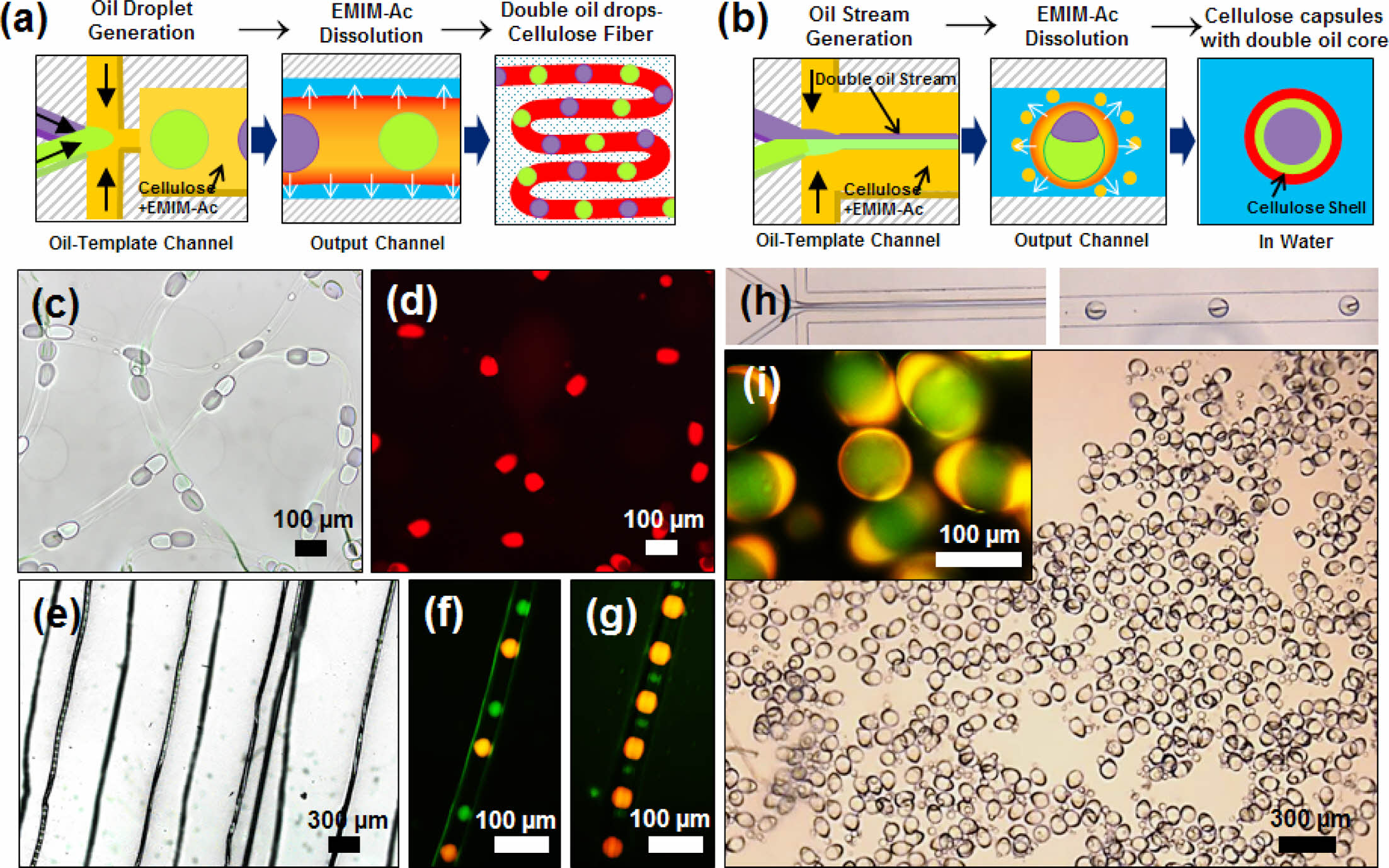
Figure 5 shows the synthetic applications of transport systems containing different materials in the cellulose fibers and capsules. A novel microfluidic device was designed to inject two oils (mineral and silicon oils). The widths of the channels for injecting the two oils, cellulose solution, and glycerol-containing water were 30, 30, 55, and 55 μm, respectively. The dimensions of the oil-template and output channels were 140 μm × 2 mm (width × length) and 140 μm × 3 mm (width × length), respectively. Cellulose microfibers and microcapsules with embedded droplets of two oils were synthesized in a microchannel, as illustrated in Figures 5(a, b). To fabricate knotted microfibers, two different oil cores were alternately injected at the same flowrate and regenerated at intervals equal to the initial intervals, as shown in Figures 5(c, d). The size of the oil droplets was determined by the flowrate ratio of the core flow, and the main factor affecting the knot spacing was QW, which is in agreement with the results in Figure 2(c). Figures 5(e–g) show the cellulose fibers produced by varying only the QOil at a constant QW of 10 μL min–1. Two oil cores with diameters of 30 μm were regenerated 200 μm apart, and injected oil droplets with diameters of 70 μm were regenerated 100 μm apart. When materials of different sizes were added to the system, the oil size alone affected the knot spacing, in contrast to the oil size, which affected the fiber space.
To fabricate cellulose microcapsules embedded with two oil droplets, two immiscible oil streams were flowed in parallel with a cellulose solution in the oil template channel. As shown in Figure 5(h), both oil streams were injected at the same rate with 2 wt% cellulose in EMIM-Ac at a QC-IL of 1.0 μL min–1. At a high flowrate of QW = 50 μL min–1, two immiscible parallel oil streams were encapsulated in a cellulose shell, with one enveloping the other. Owing to the density difference, the mineral oil surrounded the silicon oil to form the core. Figure 5(i) shows the formation of microcapsules with the two oil droplets. Therefore, we can conclude that immiscible materials can be regenerated into various cellulose microstructures in our microfluidic system by varying their flowrates. The distance between the two oils in the fiber could be regulated by controlling the injection velocities of the materials. Based on this method, a process for transporting mixed compounds synthesized from cellulose fibers can be designed. Moreover, a process can be designed in which two materials with the same flowrates are encapsulated and delivered in a synthetic state.
|
Figure 1 (a) Schematic of the microfluidic device and the generation of various oil-templated cellulose microstructures (oil droplet-embedded fibers and short threads, tubes, capsules); (b) schematic of the synthesis of oil-templated microstructures by regeneration of cellulose from EMIM-Ac in the microfluidic device; (c) phase diagram of the types of cellulose microstructures based the aqueous phase flowrate (QW) and the flowrate ratio of the oil and cellulose-containing EMIM-Ac (QOil/QC-IL). |
|
Figure 2 Cellulose microfibers orderly incorporated with oil droplets: (a) Optical microscope images of the generation of oil droplets in the oil-template channel and cellulose fibers in the output channel. From the top to the bottom images, the ratio of the volumetric flowrates of the oil and cellulose-containing EMIM-Ac (QOil/QC-IL) was 0.1, 0.2, and 0.3, respectively; the flowrate of the aqueous phase (QW) was fixed at 5.0 μL min–1. (b) Diameter of oil droplets generated in the oil-template channel and (c) distance between the droplets in the oil-template channel (■, ●, ▲) and within the cellulose fibers ( □, ○, △) as a function of QOil/QC-IL. Bright-field images of cellulose fibers in water produced at (d) QOil/QC-IL = 0.2 and QW = 1.7 μL min–1 and at (e) QOil/QC-IL = 0.2 and QW = 5.0 μL min–1. (f) Fluorescent image of the cellulose fibers on a glass slide. (g) Optical and fluorescent images of the dried cellulose fiber in (e). The oil phase and the cellulose-dissolved EMIMAc contained Oil Blue N dye, and Sudan I dye, respectively. |
|
Figure 3 (a) Optical microscope images of the typical oil stream in the oil-template channel and the generation of cellulose tube and capsules in the output channel. (b), (c) Bright-field images of the cellulose tube in water. (d) Optical and (e) fluorescent images of the dried cellulose tubes after collecting with a clip (inset); the cellulose tubes were produced at QOil/QC-IL = 1.0 and QW = 3.0 μL min–1. (f) Bright-field image of the cellulose capsules in water; the capsules were produced at QOil/QC-IL = 2.0 and QW = 100 μL min–1. (g) Diameter of the cellulose capsules as a function of the aqueous-phase flowrate (QW). (h) SEM image of the cellulose shell after removing oil core from the capsule in (f). (i) Fluorescent image of the cellulose capsules prepared at QOil/QC-IL = 4.0 and QW = 133.4 μL min–1. |
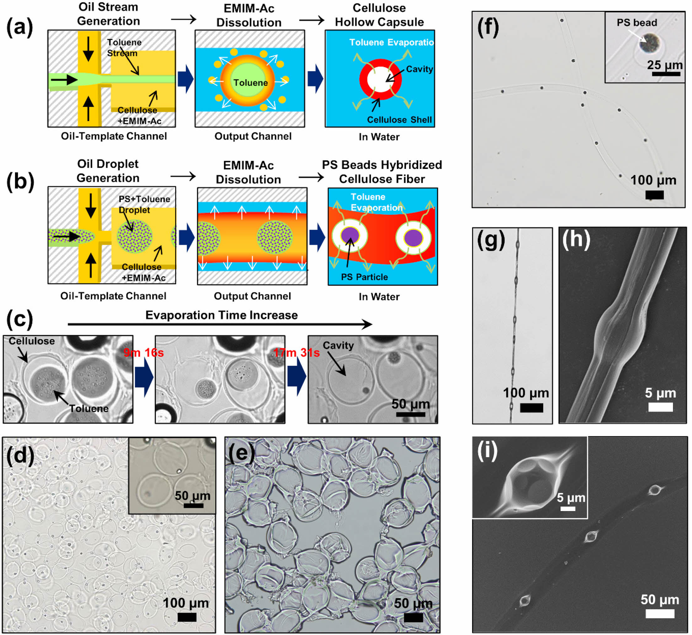
|
Figure 4 Schematics of the synthesis of (a) hollow cellulose capsules; (b) PS bead-hybridized cellulose fibers; (c) Serial bright-field images of the hollow cellulose capsules in water at increasing evaporation times of the oil core. Bright-field images of the hollow cellulose capsules when; (d) suspended in water; (e) dried. The hollow cellulose capsules were synthesized with 2 wt% cellulose in EMIM-Ac at QOil/QC-IL = 2.0 and QW = 30 μL min–1; (f) Bright-field image of PS bead-hybridized cellulose fibers in water; (g) Optical; (h) SEM images of the dried cellulose fiber orderly incorporated with the PS beads after collection with a clip; (i) SEM image of the PS bead-hybridized cellulose fiber after drying on a Si wafer. The cellulose fiber embedded with PS beads was synthesized with 2 wt% cellulose in EMIM-Ac and 10 mg mL–1 PS in toluene at QOil/QC-IL = 0.4 and QW = 10 μL min–1. |
|
Figure 5 Schematics of the synthesis of dual oil droplet-embedded: (a) cellulose fibers; (b) cellulose capsules. Bright-field images of the (c, d) dual oil droplet-embedded cellulose fibers suspended in water and (e–g) dried cellulose fibers. Hollow cellulose capsules synthesized with 2 wt% cellulose in EMIM-Ac at (f) QOil=0.1, 0.5, QC-IL=1.0, and QW=10 μL min–1; (g) QOil=0.1, 0.1, QC-IL=1.0 and QW=10 μL min–1; (h) Optical microscope images of the generation of oil droplets in the oil-template channel and cellulose capsules in the output channel; (i) Bright-field image of dual oil droplet-embedded cellulose capsules in water. The cellulose capsules embedded with two oil droplets were synthesized with 2 wt% cellulose in EMIM-Ac at QOil=0.9, QC-IL=1.0, and QW=50 μL min–1; mineral oil and silicone oil were used. |
This study proposed and developed a single-step continuous process for fabricating various microscale hybrid architectures using a single microfluidic device. The proposed method for fabricating cellulose microstructures was based on the principle of cellulose regeneration, wherein cellulose dissolved in an IL was regenerated upon exposure to an antisolvent (aqueous glycerin solution) and formed various cellulose microstructures on the oil templates. The morphology and size of the cellulose microstructures were easily controlled by varying the flowrate of each fluid, eliminating the need for complicated devices or processes. In the oil-template channel, oil was dispersed in the IL and flowed in the form of droplets or a stream. In the output channel, depending on the flow rates of the oil, cellulose solution, and glycerin aqueous solution, various cellulose microstructures, such as the fibers, tubes, and capsules, were observed. Oil droplets were produced in an orderly manner in the C-IL solution when the flowrate ratio (QOil/QC-IL) was less than 0.5. The diameter of the mineral oil droplets increased as the flow rate of the oil phase increased, and knot-shaped cellulose fibers containing oil droplets were produced when the flow rate of the aqueous phase was low. Although the water flow rate did not affect the size of the oil droplets, short threads were formed when the water flow was unstable or at a high rate. Meanwhile, to produce cellulose microtubes, it was found that the flow rate of the oil must be higher than that of the cellulose solution (QOil/QC-IL > 1.0). Then, when the water flow rate was low, the aqueous phase stably flowed out continuously in a tube shape. However, at a high water flow rate, the C-IL stream broke, resulting in the formation of capsules. The size of the cellulose microcapsules was determined based on the flow rate of the aqueous solution; the faster the flow rate of the aqueous solution, the smaller the cellulose capsule size. Subsequently, the proposed method was applied to fabricate hollow capsules and hybrid cellulose fibers containing polymer beads using a volatile solvent (toluene) instead of mineral oil. These applications offer advantages such as the production of hybrid polymeric microstructures with flexible production methods, effective fluid control, and good tunability of morphology and shape of cellulose microstructures within a single microfluidic system. Despite recent advances in this field, the proposed method expands the flexibility of the design of microfluidic systems, strategies used to produce microstructures, and processes that control the morphology and size of structures. Therefore, it can potentially enable researchers to employ various materials to produce fibers and capsules and to design structures with various functions, thereby enabling the use of cellulose in a wide range of novel industrial applications.
- 1. Eichhorn, S. J.; Dufresne, A.; Aranguren, M.; Marcovich, N. E.; Capadona, J. R.; Rowan, S. J.; Weder, C.; Thielemans, W.; Roman, M.; Renneckar, S.; Gindl, W.; Veigel, S.; Keckes,J.; Yano, H.; Abe, K.; Nogi, M.; Nakagaito, A. N.; Mangalam, A.; Simonsen, J.; Benight, A. S.; Bismarck, A.; Berglund, L. A.; Peijs, T. Review: Current International Research into Cellulose Nanofibres and Nanocomposites. J. Mater. Sci. 2010, 45, 1-33.
-

- 2. Moon, R. J.; Martini, A.; Nairn, J.; Simonsen, J.; Youngblood, J. Cellulose Nanomaterials Review: Structure, Properties and Nanocomposites. Chem. Soc. Rev. 2011, 40, 3941-3994.
-
- 3. Swatloski, R. P.; Spear, S. K.; Holbrey, J. D.; Rogers, R. D. Dissolution of Cellose with Ionic Liquids. J. Am. Chem. Soc. 2002, 124, 4974-4975.
-
- 4. Eichhorn, S. J.; Baillie, C. A.; Zafeiropoulos, N.; Mwaikambo, L. Y.; Ansell, M. P.; Dufresne, A.; Entwistle, K. M.; Herrera-Franco, P. J.; Escamilla, G. C.; Hughes, M.; Hill, C.; Rials, T. G.; Wild, P. M. Review Current International Research into Cellulosic Fibres and Composites. J. Mater. Sci. 2001, 36, 2107-2131.
-
- 5. Klemm, D.; Heublein, B.; Fink, H. P.; Bohn, A. Cellulose: Fascinating Biopolymer and Sustainable Raw Material. Angew. Chem. Int. Ed. 2005, 44, 3358-3393.
-
- 6. Azizi Samir, M. A. S.; Alloin, F.; Dufresne, A. Review of Recent Research into Cellulosic Whiskers, Their Properties and Their Application in Nanocomposite Field. Biomacromolecules 2005, 6, 612-626.
-
- 7. Fink, H.-P.; Weigel, P.; Purz, H. J.; Ganster, J. Structure Formation of Regenerated Cellulose Materials from NMMO-Solutions. Prog. Polym. Sci. 2001, 26, 1473-1524.
-
- 8. Satari, B.; Karimi, K.; Kumar, R. Cellulose Solvent-Based Pretreatment for Enhanced Second-Generation Biofuel Production: A Review. Sustain Energy. Fuels. 2019, 3, 11-62.
-
- 9. Gebbie, M. A.; Valtiner, M.; Banquy, X.; Fox, E. T.; Henderson, W. A.; Israelachvili, J. N. Ionic Liquids Behave as Dilute Electrolyte Solutions. Proc. Natl. Acad. Sci. U.S.A. 2013, 110, 9674-9679.
-
- 10. Weingärtner, H. Understanding Ionic Liquids at the Molecular Level: Facts, Problems, and Controversies. Angew. Chem. Int. Ed. 2008, 47, 654-670.
-
- 11. Fuller, J.; Carlin, R. T.; Osteryoung, R. A. The Room Temperature Ionic Liquid 1-Ethyl-3-Methylimidazolium Tetrafluoroborate: Electrochemical Couples and Physical Properties. J. Electrochem. Soc. 1997, 144, 3881-3886.
- 12. Antonietti, M.; Kuang, D.; Smarsly, B.; Zhou, Y. Ionic Liquids for the Convenient Synthesis of Functional Nanoparticles and Other Inorganic Nanostructures. Angew. Chem. Int. Ed. 2004, 43, 4988-4992.
-
- 13. Yang, C. H.; Huang, K. S.; Lin, Y. S.; Lu, K.; Tzeng, C. C.; Wang, E. C.; Lin, C. H.; Hsu, W. Y.; Chang, J. Y. Microfluidic Assisted Synthesis of Multi-Functional Polycaprolactone Microcapsules: Incorporation of CdTe Quantum Dots, Fe3O4 Superparamagnetic Nanoparticles and Tamoxifen Anticancer Drugs. Lab Chip 2009, 9, 961-965.
-
- 14. Xu, S.; Nie, Z.; Seo, M.; Lewis, P.; Kumacheva, E.; Stone, H. A.; Garstecki, P.; Weibel, D. B.; Gitlin, I.; Whitesides, G. M. Generation of Monodisperse Particles by Using Microfluidics: Control over Size, Shape, and Composition. Angew. Chem. Int. Ed. 2005, 44, 724-728.
-
- 15. Nisisako, T.; Torii, T.; Higuchi, T. Novel Microreactors for Functional Polymer Beads. Chem. Eng. J. 2004, 101, 23-29.
-
- 16. Jeong, W. J.; Kim, J. Y.; Choo, J.; Lee, E. K.; Han, C. S.; Beebe, D. J.; Seong, G. H.; Lee, S. H. Continuous Fabrication of Biocatalyst Immobilized Microparticles Using Photopolymerization and Immiscible Liquids in Microfluidic Systems. Langmuir 2005, 21, 3738-3741.
-
- 17. Nie, Z.; Li, W.; Seo, M.; Xu, S.; Kumacheva, E. Janus and Ternary Particles Generated by Microfluidic Synthesis: Design, Synthesis, and Self-Assembly. J. Am. Chem. Soc. 2006, 128, 9408-9412.
-
- 18. Zhang, H.; Ju, X. J.; Xie, R.; Cheng, C. J.; Ren, P. W.; Chu, L. Y. A Microfluidic Approach to Fabricate Monodisperse Hollow or Porous Poly(HEMA-MMA) Microspheres Using Single Emulsions as Templates. J. Colloid. Interface. Sci. 2009, 336, 235-243.
-
- 19. Eun, T. H.; Kim, S. H.; Jeong, W. J.; Jeon, S. J.; Kim, S. H.; Yang, S. M. Single-Step Fabrication of Monodisperse TiO2 hollow Spheres with Embedded Nanoparticles in Microfluidic Devices. Chem. Mater. 2009, 21, 201-203.
-
- 20. Liu, L.; Yang, J. P.; Ju, X. J.; Xie, R.; Yang, L.; Liang, B.; Chu, L. Y. Microfluidic Preparation of Monodisperse Ethyl Cellulose Hollow Microcapsules with Non-Toxic Solvent. J. Colloid. Interface. Sci. 2009, 336, 100-106.
-
- 21. Gokmen, M. T.; De Geest, B. G.; Hennink, W. E.; Du Prez, F. E. “Giant” Hollow Multilayer Capsules by Microfluidic Templating. ACS Appl. Mater. Interfaces 2009, 1, 1196-1202.
-
- 22. Hwang, C. M.; Khademhosseini, A.; Park, Y.; Sun, K.; Lee, S. H. Microfluidic Chip-Based Fabrication of PLGA Microfiber Scaffolds for Tissue Engineering. Langmuir 2008, 24, 6845-6851.
-
- 23. Chen, C.; Zhao, Y.; Liu, W. Electrospun Polyethylene Glycol/Cellulose Acetate Phase Change Fibers with Core-Sheath Structure for Thermal Energy Storage. Renew Energy 2013, 60, 222-225.
-
- 24. Kang, E.; Jeong, G. S.; Choi, Y. Y.; Lee, K. H.; Khademhosseini, A.; Lee, S. H. Digitally Tunable Physicochemical Coding of Material Composition and Topography in Continuous Microfibres. Nat. Mater. 2011, 10, 877-883.
-
- 25. Jeong, W.; Kim, J.; Kim, S.; Lee, S.; Mensing, G.; Beebe, D. J. Hydrodynamic Microfabrication via “on the Fly” Photopolymerization of Microscale Fibers and Tubes. Lab. Chip. 2004, 4, 576-580.
-
- 26. Whitesides, G. M. The Origins and the Future of Microfluidics. Nature 2006, 442, 368-373.
-
- 27. Halldorsson, S.; Lucumi, E.; Gómez-Sjöberg, R.; Fleming, R. M. T. Advantages and Challenges of Microfluidic Cell Culture in Polydimethylsiloxane Devices. Biosens. Bioelectron. 2015, 63, 218-231.
-
- 28. Fu, L.; Ju, Z.; Yu, M.; Luo, H.; Zhang, C.; Zhang, X.; Cheng, H.; Zheng, M.; Jin, L.; Ge, C. Cellulose Regeneration in Imidazolium-Based Ionic Liquids and Antisolvent Mixtures: A Density Functional Theory Study. ACS Omega 2022, 7, 42170-42180.
-
- 29. Binary Solvent Mixtures of an Ionic Liquid and Water. J. Phys. Chem. B 2011, 115, 10251-10258.
- 30. Nunes, J. K.; Tsai, S. S. H.; Wan, J.; Stone, H. A. Dripping and Jetting in Microfluidic Multiphase Flows Applied to Particle and Fibre Synthesis. J. Phys. D Appl. Phys. 2013, 46.
-
- 31. Oh, H. J.; Kim, S. H.; Baek, J. Y.; Seong, G. H.; Lee, S. H. Hydrodynamic Micro-Encapsulation of Aqueous Fluids and Cells via “on the Fly” Photopolymerization. J. Micromech. Microeng. 2006, 16, 285-291.
-
- 32. Hudson, S. D.; Cabral, J. T.; Goodrum, W. J.; Beers, K. L.; Amis, E. J. Microfluidic Interfacial Tensiometry. Appl. Phys. Lett. 2005, 87.
-
- 33. Cabral, J. T.; Hudson, S. D. Microfluidic Approach for Rapid Multicomponent Interfacial Tensiometry. Lab Chip 2006, 6, 427-436.
-
- 34. Ji, X.; Guo, S.; Zeng, C.; Wang, C.; Zhang, L. Continuous Generation of Alginate Microfibers with Spindle-Knots by Using a Simple Microfluidic Device. RSC Adv. 2015, 5, 2517-2522.
-
- 35. Dong, H.; Wang, N.; Wang, L.; Bai, H.; Wu, J.; Zheng, Y.; Zhao, Y.; Jiang, L. Bioinspired Electrospun Knotted Microfibers for Fog Harvesting. Chem. Phys. Chem. 2012, 13, 1153-1156.
-
- 36. Bai, H.; Ju, J.; Sun, R.; Chen, Y.; Zheng, Y.; Jiang, L. Controlled Fabrication and Water Collection Ability of Bioinspired Artificial Spider Silks. Adv. Mater. 2011, 23, 3708-3711.
-
- 37. He, X. H.; Wang, W.; Liu, Y. M.; Jiang, M. Y.; Wu, F.; Deng, K.; Liu, Z.; Ju, X. J.; Xie, R.; Chu, L. Y. Microfluidic Fabrication of Bio-Inspired Microfibers with Controllable Magnetic Spindle-Knots for 3D Assembly and Water Collection. ACS Appl Mater Interfaces 2015, 7, 17471-17481.
-
- 38. Tian, Y.; Zhu, P.; Tang, X.; Zhou, C.; Wang, J.; Kong, T.; Xu, M.; Wang, L. Large-Scale Water Collection of Bioinspired Cavity-Microfibers. Nat. Commun. 2017, 8.
-
- 39. Hou, Y.; Chen, Y.; Xue, Y.; Zheng, Y.; Jiang, L. Water Collection Behavior and Hanging Ability of Bioinspired Fiber. Langmuir 2012, 28, 4737-4743.
-
- 40. Um, E.; Nunes, J. K.; Pico, T.; Stone, H. A. Multicompartment Microfibers: Fabrication and Selective Dissolution of Composite Droplet-in-Fiber Structures. J. Mater. Chem. B 2014, 2, 7866-7871.
-
- 41. Kim, S. T.; Cho, S. R.; Song, M.; Chang, S. T. Microfluidic Synthesis of Microfibers Based on Regeneration of Cellulose from Ionic Liquids. Polym. Korea 2015, 39, 588-592.
-
- Polymer(Korea) 폴리머
- Frequency : Bimonthly(odd)
ISSN 0379-153X(Print)
ISSN 2234-8077(Online)
Abbr. Polym. Korea - 2023 Impact Factor : 0.4
- Indexed in SCIE
 This Article
-
2024; 48(2): 242-252
Published online Mar 25, 2024
- 10.7317/pk.2024.48.2.242
- Received on Dec 20, 2023
- Revised on Dec 29, 2023
- Accepted on Dec 29, 2023
Services
- Full Text PDF
- Abstract
- ToC
- Acknowledgements
- Conflict of Interest
- Supporting Information
Introduction
Experimental
Results and Discussion
Conclusions
- References
Shared
Correspondence to
- Suk Tai Chang
-
School of Chemical Engineering and Materials Science, Chung-Ang University, 84 Heukseok-ro, Dongjak-gu, Seoul 06974, Korea
- E-mail: stchang@cau.ac.kr
- ORCID:
0000-0002-1372-8872
Hyecheon Building(Room 601), #354, Gangnam-Daero, Gangnam-Gu, Seoul 06242, Korea
TEL : 82-2-568-3860, 561-5203, 569-3860 FAX : 82-2553-6938 E-mail: polymer@polymer.or.kr