


- Failure Analysis of High-density Polyethylene Pipe in Heat-transport Infrastructure of District Heating System
Hobyung Chae, Min Ji Song*, and Soo Yeol Lee*,†

Neutron Science Division, Korea Atomic Energy Research Institute, Daejeon 34057, Korea
*Department of Materials Science and Engineering, Chungnam National University, Daejeon 34134, Korea- 지역난방 시스템의 열 수송 기반 시설 내 HDPE 관 파손 분석
채호병 · 송민지* · 이수열*,†
한국원자력연구원중성자과학부,*충남대학교신소재공학과
Reproduction, stored in a retrieval system, or transmitted in any form of any part of this publication is permitted only by written permission from the Polymer Society of Korea.
District heating systems provide heat to users through heat-transport infrastructure, which typically consists of steel pipe for transporting hot water, polyurethane foam to prevent heat loss, and high-density polyethylene (HDPE) pipe to protect against external shock and contamination. Failures of HDPE can lead to contamination, insulator hydrolysis, and water vapor leakage. This study investigates the failure of a HDPE cover cap that is composed of ring- and disk-shaped HDPE components joined using fused PE. A critical crack was found on the interface between the ring and fused PE, allowing external earth and water to flow into the interior of the HDPE pipe. A tensile test to examine the mechanical behavior and adhesion strength between interfaces showed that the mechanical performance was diminished due to foreign substances and pores on the interface. Based on these findings, recommendations for manufacturing and managing HDPE components are suggested as countermeasures to prevent future failures.
지역난방시스템에서 열은 열 수송 시설을 통해 사용자 측에 공급되고 있으며, 열 수송 시설은 온수를 공급하는 강관, 열 손실을 막는 폴리우레탄 폼, 이를 외부 충격과 오염으로부터 보호하는 고밀도 폴리에틸렌관으로 구성된다. 고밀도 폴리에틸렌관의 파손은 관 내 오염과 보온재의 열화, 수증기 누수 등으로 이어질 수 있다. 본 연구는 고밀도 폴리에틸렌관의 부품인 커버 캡의 파손을 다룬다. 커버 캡의 링 모양 부품과 접합 폴리에틸렌의 경계면에서 주요한 균열이 발견되었고, 이를 통해 시스템의 효율을 저하시키는 외부 오염 물질이 관 내로 유입되었다. 인장 실험을 통해 부품의 건전성 및 부품 간 접합 강도를 평가한 결과, 커버 캡 제작 중 유입된 외부 물질과 기포로 인해 기계적 강도가 저하된 것이 확인되었다. 본 연구는 폴리에틸렌관 부품의 생산 및 관리 방법 개선을 통해 유사한 파손을 예방하는데 있어서 도움이 될 것으로 기대된다.
This study deals with the failure analysis of a high-density polyethylene (HDPE) cover cap in heat-transport infrastructure of district heating system. The foreign substances and pores found on the interface between the ring and fused polyethylene diminished the adhesion strength, leading to crack formation followed by a leakage.
Keywords: district heating system, heat-transport, high-density polyethylene, failure.
This work was supported by Korea District Heating Corporation. HC was supported by the Korea Institute of Energy Technology Evaluation and Planning (KETEP) and the Ministry of Trade, Industry, and Energy (MOTIE) (No. 20223030030110).
The authors declare that there is no conflict of interest.
District heating systems are becoming increasingly popular due to their eco-friendliness and efficient heat delivery to urban areas from centralized heat-generating facilities.1 The heat-transport infrastructure is a core part of this system, and its proper functioning is essential for maintaining stable and reliable heat delivery to end-users. However, due to its underground location, the heat-transport infrastructure is vulnerable to external forces, corrosive environments, and other adverse factors, making it challenging to manage and maintain.2-6 Failures in heat-transport infrastructure can result in severe heat loss, as well as dangerous accidents in urban areas.7-15 Therefore, it is crucial to examine safety-related factors in detail and develop effective countermeasures.
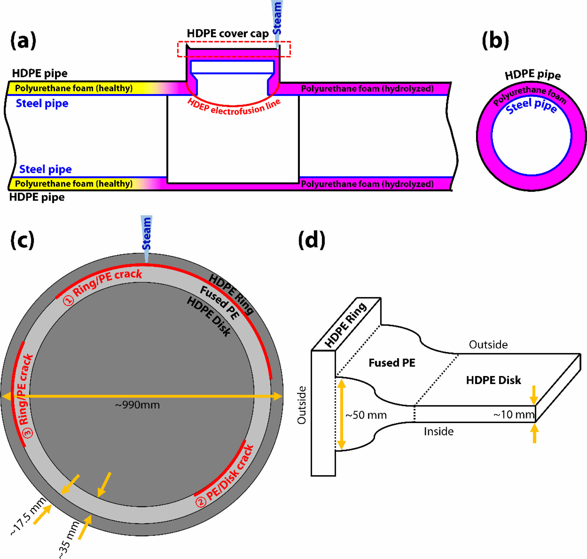
The heat-transport infrastructure comprises steel pipe for transporting hot water, polyurethane foam for insulation, and high-density polyethylene (HDPE) pipe for protecting the steel pipe and polyurethane foam (Figures 1(a), (b)). HDPE is widely used as a covering material due to its excellent corrosion/erosion resistance and insulation properties.8,16 The melt flow index of HDPE used in this environment is typically regulated to be less than ~1.6 g/10 min. During installation, the steel and HDPE pipes are installed first, and polyurethane foam is injected into the vacant space between both pipes. The HDPE cover cap is then electro-fused to the HDPE pipe after pre-heating to 270-280 ℃ (Figure 1(a)).17-20 An air pressure test of 2 bar for two minutes is then conducted to ensure proper electro-fusion between the HDPE cover cap and the HDPE pipe.
The HDPE cover cap comprises a ring-shaped component (HDPE ring hereafter) and a disk-shaped component (HDPE disk hereafter), which are joined using fused PE (fused PE hereafter) after pre-heating (Figures 1(c), (d)). Failure of the HDPE cover cap can result in insulator damage and corrosion of the steel pipe due to the infiltration of corrosive or foreign materials, leading to heat loss and, in extreme cases, leakage of hot water.21
This study investigates the failure of a HDPE cover cap discovered during maintenance of heat-transport infrastructure. A damaged HDPE cover cap was found due to steam leakage from the ground, where partially hydrolyzed polyurethane foam insulation was found (Figure 1(a)). Although the steel pipe was not fractured, the hot water of 100-115 ℃ in the steel pipe caused water from the external environment to vaporize and leak through the major crack in the HDPE cover cap. Since the location of this failure is adjacent to a river, the heat-transport pipe can be easily exposed to water. This study analyzes the failure of the HDPE component and identifies the reasons for the failure to establish a criterion for the soundness of the HDPE component. The findings of this study can be helpful in developing effective countermeasures for preventing future failures of the HDPE cover cap.
|
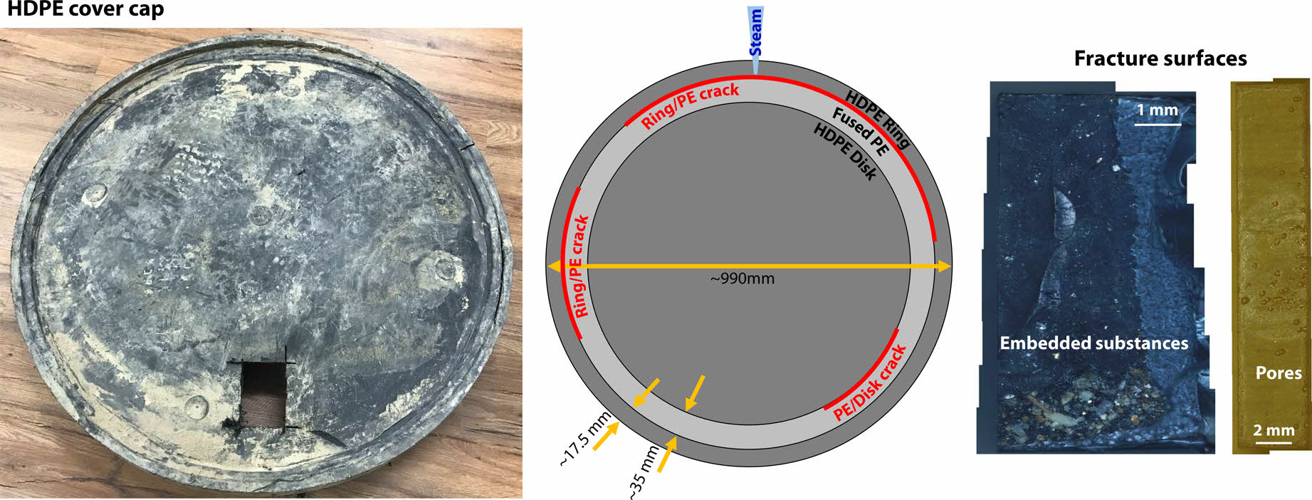
Figure 1 (a, b) Cross-sectional structures of heat-transport infrastructure with HDPE cover cap showing steam leakage; (c) structure of HDPE cover cap with crack positions; (d) its cross-sectional structure. |
Materials and Methods.The component that failed in the heat-transport infrastructure is an HDPE cover cap, as indicated by the red dashed-line rectangle in Figure 1(a). The diameter of the HDPE cover cap is approximately 990 mm, and it is composed of an HDPE ring with a width of ~17.5 mm, fused PE with a width of 35 mm, and an HDPE Disk with a thickness of 10 mm (Figures 1(c), (d)). The joint lengths in the thickness direction of the Fused PE with the HDPE Ring and the Disk are approximately ~50 mm (HDPE Ring side) and ~10 mm (HDPE disk side), respectively (Figure 1(d)). The failed HDPE cover cap exhibited three main cracks, which were located at the interfaces between the ring and fused PE (cracks 1, 2), and the fused PE and the Disk (crack 3) (Figure 1(c)). Since crack 1 was considered critical damage due to steam leaked position, it was intensively analyzed.
To establish an overall analysis plan, visual inspection of the HDPE cover cap was conducted to determine its fracture tendency. Tensile tests (Customized UTM, R&B, Korea) were performed with a crosshead speed of 10 mm/min to measure the tensile behavior and adhesion strength of each component in order to examine the soundness of the HDPE cover cap. Optical microscopy (OM, Olympus, Japan) and scanning electron microscopy (SEM, Testcan Clara, Czech Republic) were used to observe its fractography, while energy dispersive spectroscopy (EDS) was utilized to evaluate the contamination of the HDPE surfaces
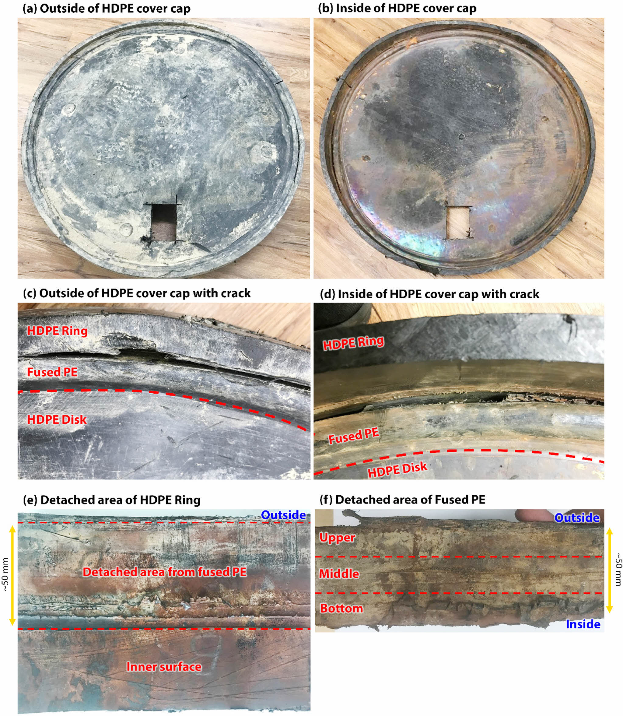
Visual Inspection. The outside and inside views of the failed HDPE cover cap are presented in Figures 2(a) and (b), respectively. The outside surface of the cover cap was contaminated with earth and sand due to its location buried in the ground, and scales were deposited on the inner surface. Crack 1 was located at the clockwise 11-3 position (steam direction: clockwise 12), while crack 2 and crack 3 were located at the clockwise 5 and 9 positions, respectively (Figure 1(c)). Crack 1 was visible on both the outside and inside of the HDPE cover cap, indicating that it allowed foreign substances to enter from the external environment to the interior of the HDPE pipe (Figures 2(c) and (d)). In contrast to Figure 2(c), Figure 2(d) shows PE debris on the fused PE between the HDPE ring and fused PE. To observe the detached area of the HDPE ring and fused PE, a portion of the cover cap was machined, as shown in Figures 2(e) and (f). The area of the HDPE ring glued to the fused PE was indicated by red dash lines (Figure 2(e)). The detached area was found to be heavily contaminated with foreign substances such as earth and sand, indicating prolonged exposure to contamination. PE debris similar to that seen in Figure 2(d) was also observed in the detached area of the HDPE ring and the fused PE.
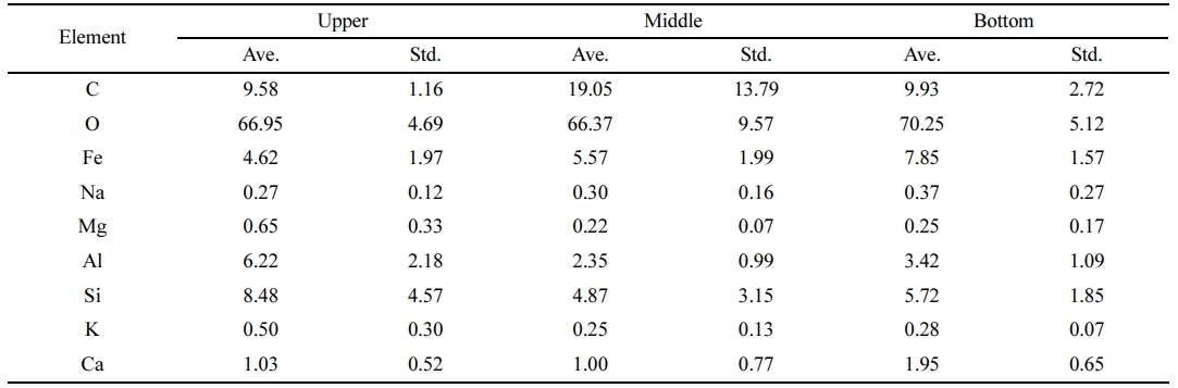
An EDS analysis was performed on the detached areas of the HDPE ring and fused PE to investigate the substances that infiltrated the HDPE pipe through the main crack. A red-colored contaminant was observed on the detached area of the HDPE ring (Figure 2(e)), which was identified to be iron oxide (Table 1). Iron ions dissolved from the steel pipe might have flowed out and into the HDPE pipe, and subsequently deposited on the inner surface as hematite. Other elements found in the contaminant may have originated from the surrounding soil.22,23 To examine the contamination tendency in the detached area of the Fused PE, the region was divided into three sections (upper, middle, and bottom) and analyzed using EDS (Figure 2(f)). The results showed that while iron was detected in higher concentrations in the bottom region, the upper region also exhibited higher concentrations of aluminum and silicon (Table 2). These findings are consistent with the results of visual inspection, which indicated that both internal and external substances had been flowing out and in, respectively, via the crack for an extended period of time.
Tensile Properties and Adhesion Strength. In order to investigate the root cause of the main crack at the ring/fused PE interface, tensile tests on each component of the cover cap (ring, fused PE, and disk) were conducted. Additionally, three-layered tensile specimens (denoted hereafter as 3-Layers) were prepared to estimate the adhesion strength at the ring/fused PE/Disk interfaces. The interfaces were located within the gauge length of the specimens for tensile tests. These measurements are necessary to identify any weak points or defects among the individual components and their interfaces, because those could be potential sites leading to crack initiation and propagation.
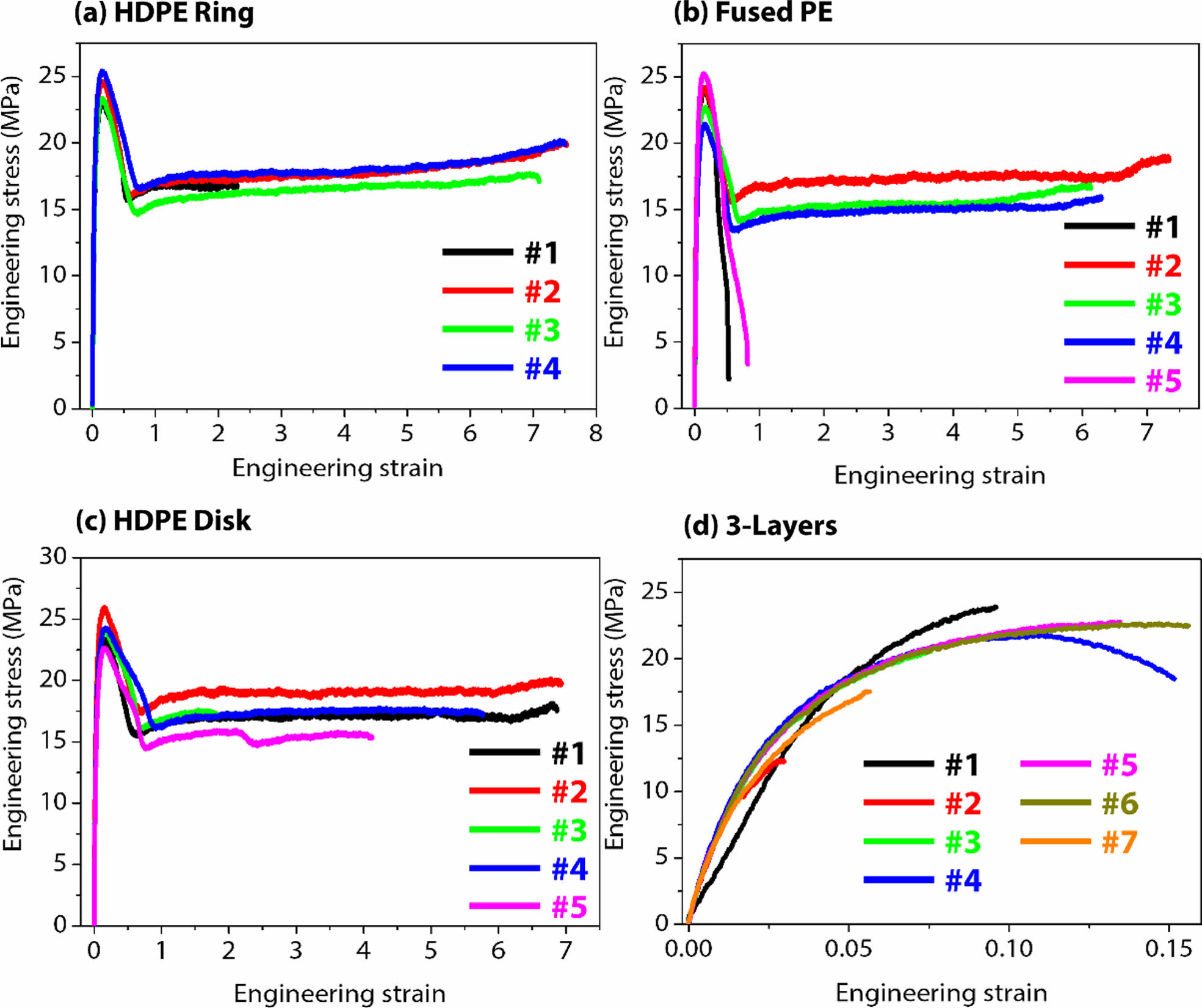
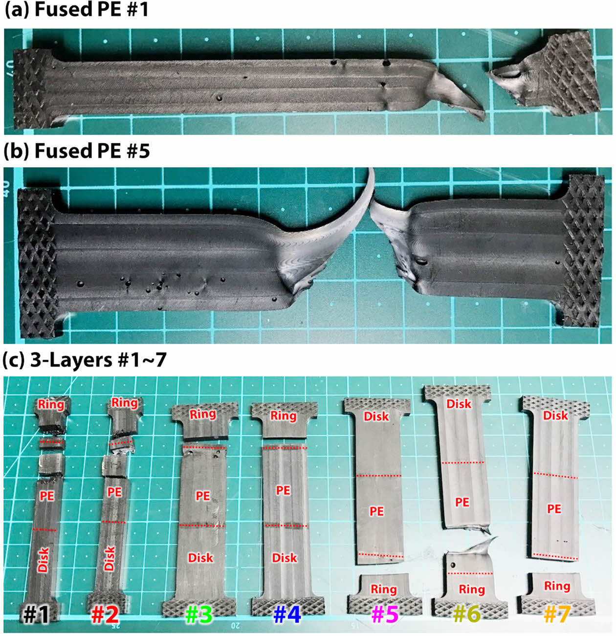
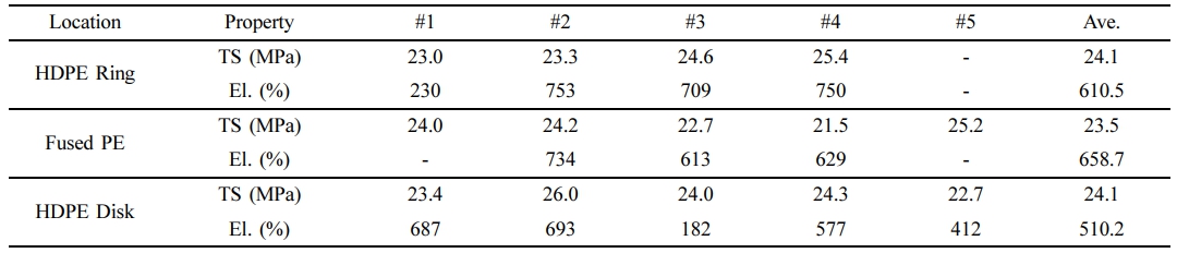
The tensile test results for each component of the cover cap are presented in Figure 3 and summarized in Table 3. Note that the number of tensile samples (#n) indicates the number of tests for reproducibility. The stress-strain curves for each component displayed typical five-step tensile behaviors consisting of elastic deformation, necking (strain softening), cold drawing, strain hardening, and failure.24,25 Although the distinction between the cold drawing and strain hardening steps was not clear, they appeared to occur simultaneously in a mixed state. The HDPE ring exhibited a distinct stress drop after reaching an average tensile strength of 24.1 MPa, followed by typical elongation behavior of a soft material with further strain. This component then fractured at a strain of 610.5% (since the tensile strength is identical to the yield strength, both strengths were denoted as tensile strength). The average tensile strength of the five fused PE specimens was 23.5 MPa (Figure 3(b)). While #1 and #5 failed immediately after necking with a rapid stress drop without undergoing the cold drawing step, #2-4 were strained until reaching an average strain of 658.7%, similar to the HDPE ring. Although all the tensile specimens were machined from inside the HDPE cover cap, pores were observed on specimens #1 and #5 (see Figures 4(a), (b)), unlike #2-4, which may have had a disadvantageous effect on their mechanical behavior. The HDPE disk exhibited similar tensile behavior to the Ring, with a tensile strength of 24.1 MPa and elongation of 510.2% (Figure 3(c)).
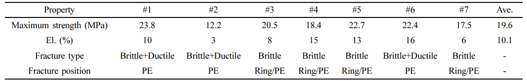
The results of the tensile tests for the 3-layers are presented in Figure 3(d) and Table 4. To avoid distortion induced by the effects of the cross-head direction, samples #1-4 and #5-7 were installed with the ring part and disk part facing the cross-head direction, respectively, and then pulled during the tensile test. Most of the specimens failed before necking, revealing an average maximum strength of 19.6 MPa. Excluding specimens #2 and #7, which exhibited the weakest strength, the maximum strength for the others averaged 21.6 MPa, which is approximately 90% of the tensile strength of the HDPE components. However, the elongation for the 3-Layers averaged only 10.1%, indicating significantly lower ductility. The degraded tensile properties can be interpreted from the fracture tendency and fractography. Figure 4(c) shows the 3-Layers samples that were subjected to the tensile test, with red dashed lines indicating each interface. Specimens #1, #2, and #6 failed with a brittle and ductile fracture mode in the fused PE part near the Ring part, displaying fracture debris induced by severe necking, similar to Fused PE specimen #5 (Figure 4(b)). In contrast, specimens #3-5 and #7 failed with a brittle fracture mode on the Ring/PE interface, showing a flat fracture surface. As observed in Figures 4(a) and (b), pores were also present in the fused PE (Figure 4(c)), and severe necking near pores were observed in specimen #3, indicating that the applied stress was concentrated on the area surrounding the pores. Obviously, pores can deteriorate the mechanical properties of the HDPE component. However, the observation of the fracture occurring on the Ring/PE interface rather than in the area surrounding the pores indicates that this interface is more vulnerable than the components and the PE/Disk interface.
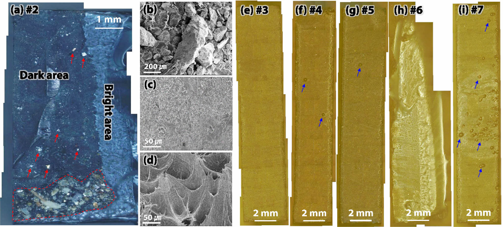
The fracture surface of 3-Layers sample #2 was analyzed to determine why it exhibited the lowest mechanical behavior with a maximum strength of 12.2 MPa and elongation of 3% (Figure 3(d), Table 4). The fracture surface contained foreign substances embedded in the material, with sizes ranging from 50-500 μm, indicated by red-dash lines and arrows in Figure 5(a). The EDS analysis revealed that these foreign substances were earth and sand, as indicated by the high content of carbon and the detection of sodium, aluminum, and silicon (Table 5).23 Inflow of these foreign materials likely occurred during the manufacturing process, as it is difficult for foreign material to enter the material after installation of the HDPE cover cap. The fracture is believed to have initiated at the position where sand was embedded, and the crack propagated through the dark area in a brittle manner, leading to failure at the bright area in a ductile manner.8,25,26 Fracture behaviors can be observed in Figures 5(c) and (d), with smooth surfaces on the dark area and severe sheared dimples on the bright area, respectively. The existence of foreign substances and pores (blue arrows) with sizes ranging from 150-300 μm on fracture surfaces #4, #5, and #7, respectively, led to lower maximum strength and brittle fracture at the interface (Figures 5(f), (g), (i)). These results suggest that foreign substances and the number of pores are crucial factors that reduce tensile properties. Their presence reduces the cross-sectional area, causing stress concentration in these areas, which diminishes adhesion of the Fused PE and ultimately leads to degraded tensile properties.
Among the HDPE components, fused PE exhibited lower performance when it contained pores, and the ring/PE interface was found to be particularly vulnerable based on the results of the 3-layers test. This is attributed to the manufacturing characteristics of the HDPE cover cap. While the ring and disk components are produced by injection molding, the process for fused PE used for joining both components is carried out in an outdoor environment and is subject to rapid environmental changes, which can lead to the formation of interior pores and to contamination. Therefore, crack 1 (Figure 1(c)) was initiated from the ring/PE interface, where the Fused PE on the Ring-side showed low maximum strength and toughness, even with low impact. The ductile and brittle fracture behaviors displayed by the HDPE components and the 3-layers specimens revealed that the cracks rapidly propagated and thinly stretched failure debris was left after necking during fracture, indicating the direction of failure. While crack 1 showed a relatively flat surface on the outside of the detached surface, fracture debris remained on the inside (Figures 2(d)-(f)), indicating that the crack was initiated from the outside and propagated inward. In summary, cracks were generated from the outside of the ring/PE interface, diminished by pores and foreign substances, and propagated along the thickness direction. External force was concentrated on the fused PE, which is weaker than the interface, and the HDPE cover cap ultimately failed, showing ductile fracture behavior.
Based on the analysis results, we propose the following countermeasures to prevent the failure of HDPE pipes and cover caps in heat-transport infrastructure. First, the manufacturing environment for HDPE components should be carefully controlled to minimize the generation of pores and foreign substances. Special attention should be given to optimizing manufacturing conditions when fusing the ring and disk by PE, as this process is particularly vulnerable to the generation of interior pores. Alternatively, electro-fusion could be employed, as it results in enhanced adhesion strength compared to fused PE. Second, after the cover cap is joined to the HDPE pipe, air pressure tests and external impact tests corresponding to 20 MPa in strength should be conducted to ensure the integrity of the components. Finally, we recommend that the mechanical performance results of each component and interface evaluated in this study should be utilized to predict the load limitations of HDPE pipes and cover caps in future designs. By implementing these measures, it will be possible to enhance the reliability and durability of HDPE components used in heat-transport infrastructure.
|
Figure 2 Outside, inside, and detailed views of the failed HDPE cover cap: (a) outside; (b) inside of the cover cap; (c) outside; (d) inside views of detachment between each component, and the detached surfaces; (e) HDPE Ring; (f) fused PE. |
|
Figure 3 Tensile responses of (a) HDPE ring; (b) fused PE; (c) HDPE disk; (d) 3-layers machined from the HDPE cover cap. |
|
Figure 4 Fracture morphologies for (a) specimens #1; (b) #5 which are the fused PE samples; (c) specimens #1-7 which are 3-Layers samples. |
|
Figure 5 Fracture surfaces of the tensile-tested 3-layers samples shown in Figure 4(c). |
|
Table 1 EDS Results of Scale on the Detached Surface of HDPE Ring (Figure 2(e)) (at.%) |

|
Table 2 EDS Results of Scale on the Detached Surface of Fused PE (Figure 2(f)) (at.%) |
|
Table 5 EDS Results of Foreign Substance Embedded in Fracture Surface Shown in Figure 5(a) (at.%) |

In this study, the failure of an HDPE pipe in heat-transport infrastructure was investigated. The most vulnerable position in the HDPE cover cap was found to be the interface between the HDPE ring and fused PE, where a crack was initiated and propagated into the interior, leading to the inflow of external earth and water. This contamination hydrolyzed the insulator and induced outflow of steam and heat loss. To prevent such failures, optimizing the joining process between the ring and disk using fused PE, improving the manufacturing environment, and employing electro-fusion to enhance adhesion strength are recommended.
- 1. Lund, H.; Thorsen, J. E.; Svendsen, S.; Werner, S.; Hvelplund, F.; Mathiesen, B. V.; Wiltshire, R. 4th Generation District Heating (4GDH). Energy 2014, 68, 1-11.
-

- 2. Kim, Y.-S.; Kim, W.-C.; Kim, J.-G. Influence of Ultrasonic Nanocrystal Surface Modification on the Corrosion and Stress Corrosion Cracking Behavior of Low Carbon Steel (ASTM A139) Welded Joint in the Simulated District Heating Environment. Corrosion 2017, 74, 112-122.
-
- 3. Sernhed, K.; Jönsson, M. Risk Management for Maintenance of District Heating Networks. In Energy Procedia; Elsevier B. V., 2017, 116, 381-393.
-
- 4. Lidén, P.; Adl-Zarrabi, B. Non-Destructive Methods for Assessment of District Heating Pipes: A Pre-Study for Selection of Proper Methods. In Energy Procedia; Elsevier B. V., 2017, 116, 374-380.
-
- 5. Hong, M.; Chae, H.; Kim, Y.; Song, M. J.; Cho, J.; Kim, W. C.; Ha, T. B.; Lee, S. Y. Flow-Accelerated Corrosion Analysis for Heat Recovery Steam Generator in District Heating System. Korean J. Mater. Res. 2019, 29, 11-15.
-
- 6. Hong, M.; Chae, H.; Kim, W. C.; Kim, J.-G.; Kim, H.; Lee, S. Y. Failure Analysis of a Water Wall Boiler Tube for Power Generation in a District Heating System. Met. Mater. Int. 2019, 25, 1191-1201.
-
- 7. Huang, E.-W.; Lee, S. Y.; Jain, J.; Tong, Y.; An, K.; Tsou, N.-T.; Lam, T.-N.; Yu, D.; Chae, H.; Chen, S.-W.; Chen, S.-M.; Chou, H.-S. Hardening Steels by the Generation of Transient Phase Using Additive Manufacturing. Intermetallics 2019, 109, 60-67.
-
- 8. Hsuan, Y. G.; McGrath, T. J. NCHRP Report 429: HDPE Pipe: Recommended Material Specifications and Design Requirements; Transportation Research Board: Washington, DC, 1999.
- 9. Zhang, J. Experimental Study of Stress Cracking in High Density Polyethylene Pipes; Drexel University: Philadelphia 2005.
- 10. Zhao, J. Q.; Daigle, L.; Beaulieu, D. Effect of Joint Contamination on the Quality of Butt-Fused High-Density Polyethylene (HDPE) Pipe Joints. Can. J. Civ. Eng. 2002, 29, 787-798.
-
- 11. Song, M. J.; Kim, W. C.; Kim, H.; Kim, J.; Lee, S. Y. Corrosion Failure Analysis of a Biogas Pipe. 2023, 36, 153-160.
- 12. Song, M. J.; Choi, G.; Kim, W. C.; Lee, S. Y. Corrosion Protective Method Applicable to Air Vent Connected with a Heat Transport Pipe. Corros. Sci. Technol. 2023, 22, 115-122.
- 13. Cho, J.; Chae, H.; Kim, H.; Kim, J. G.; Kim, W. C.; Lee, S. Y. Failure Analysis of Stress Reliever in Heat-Transport Pipe of District Heating System. Corros. Sci. Technol. 2022, 21, 243-249.
- 14. Chae, H.; Kim, W. C.; Kim, H.; Kim, J. G.; Lee, S. Y. Failure Analysis of an Inlet Pipe of a Governor Valve in a Steam Turbine of a District Heating System. Corros. Sci. Technol. 2022, 21, 62-67.
-
- 15. Kim, Y. S.; Chae, H.; Kim, W. C.; Jeong, J. C.; Kim, H.; Kim, J.-G.; Lee, S. Y. Failure Analysis on Localized Corrosion of Heat Transport Pipe in District Heating System. Corros. Sci. Technol. 2020, 19, 122-130.
-
- 16. Olsson, M.; Jarfelt, U.; Fröling, M.; Ramnäs, O. The Polyethylene Casing as Diffusion Barrier for Polyurethane Insulated District Heating Pipes. Cell. Polym. 2001, 20, 37-48.
-
- 17. Potts, C. G.; Draaijer, L. M. Developments in Rigid Polyurethane Foams for the Insulation of District Heating Pipelines. J. Cell. Plast. 1985, 21, 51-57.
-
- 18. Başoĝul, Y.; Keçebaş, A. Economic and Environmental Impacts of Insulation in District Heating Pipelines. Energy 2011, 36, 6156-6164.
-
- 19. Skagestad, B.; Mildenstein, P. District Heating and Cooling Connection Handbook; NOVEM; Netherlands Agency for Energy and the Environment: Sittard, 2002.
- 20. Mangs, S. Insulation Materials in District Heating Pipes Environmental and Thermal Performance of Polyethylene Terephthalate and Polyurethane Foam. Doktorsavhandlingar vid Chalmers Tek. Hogsk. 2005, 2382, 1-76.
- 21. Javaherdashti, R. Corrosion under Insulation (CUI): A Review of Essential Knowledge and Practice. J. Mater. Sci. Surf. Eng. 2014, 1, 36-43.
- 22. Torrent, J.; Schwertmann, U.; Fechter, H.; Alferez, F. Quantitative Relationships between Soil Color and Hematite Content. Soil Sci. 1983, 136, 354-358.
-
- 23. Pettijohn, F. J. Chemical Composition of Sandstones-Excluding Carbonate and Volcanic Sands. In Data of Geochemistry; Fleischer, M., Ed.; United States Goverment Printing Office, Washington, 1963; pp 1-19.
-
- 24. Merah, N.; Saghir, F.; Khan, Z.; Bazoune, A. Effect of Temperature on Tensile Properties of HDPE Pipe Material. Plast. Rubber Compos. 2006, 35, 226-230.
-
- 25. Ryu, H. W.; Han, J. J.; Kim, Y. J.; Kim, J. S.; Kim, J. H.; Jang, C. H. Development of a Short-Term Failure Assessment of High Density Polyethylene Pipe Welds - Application of the Limit Load Analysis - Application O. Trans. Korean Soc. Mech. Eng. A 2015, 39, 405-413.
-
- 26. Krishnaswamy, R. K. Analysis of Ductile and Brittle Failures from Creep Rupture Testing of High-Density Polyethylene (HDPE) Pipes. Polymer 2005, 46, 11664-11672.
-

- Polymer(Korea) 폴리머
- Frequency : Bimonthly(odd)
ISSN 0379-153X(Print)
ISSN 2234-8077(Online)
Abbr. Polym. Korea - 2023 Impact Factor : 0.4
- Indexed in SCIE
 This Article
-
2024; 48(4): 376-383
Published online Jul 25, 2024
- 10.7317/pk.2024.48.4.376
- Received on Dec 21, 2023
- Revised on Feb 19, 2024
- Accepted on Apr 19, 2024
Services
- Full Text PDF
- Abstract
- ToC
- Acknowledgements
- Conflict of Interest
Introduction
Experimental
Results and Discussion
Conclusions
- References
Shared
Correspondence to
- Soo Yeol Lee
-
Department of Materials Science and Engineering, Chungnam National University, Daejeon 34134, Korea
- E-mail: sylee2012@cnu.ac.kr
- ORCID:
0009-0005-0744-4119
Hyecheon Building(Room 601), #354, Gangnam-Daero, Gangnam-Gu, Seoul 06242, Korea
TEL : 82-2-568-3860, 561-5203, 569-3860 FAX : 82-2553-6938 E-mail: polymer@polymer.or.kr