


- Effect of Compression Molding Process on Tribological Properties of PTFE/UHMWPE Composites with Different Ratios
Chen Yaping*,**, Wang Yihan*,**, Luo Xiaoshuang*,**, Yang Tian*,**, Ma Lixin*,**,Liu Lian*,** and Jia Dan*,**,†

*State Key Laboratory of Special Surface Protection Materials and Application Technology,
China Academy of Machinery Wuhan Research Institute of Materials Protection Co., Ltd.
**Hubei Longzhong Laboratory- 압축 성형 공정이 다양한 PTFE/UHMWPE 조성비 복합재의 마찰학적 특성에 미치는 영향
Reproduction, stored in a retrieval system, or transmitted in any form of any part of this publication is permitted only by written permission from the Polymer Society of Korea.
Polytetrafluoroethylene (PTFE)/ultra-high molecular weight polyethylene (UHMWPE) composites with different content ratios were fabricated using compression molding techniques, while considering molding parameters. Both the PTFE content and molding parameters had a significant effect on the tribological properties of the composites under dry sliding conditions, as confirmed by Fourier-transform infrared spectroscopy (FTIR), differential scanning calorimetry (DSC), and scanning electron microscopy (SEM). The optimal anti-friction and wear resistance behaviors for composites were achieved with molding parameters of a heating temperature of 160 °C, pressing temperature of 80 °C, and pressing pressure of 10 MPa. For PTFE/UHMWPE (10/90) at different process parameters, its wear mechanism was mainly due to spalling of PTFE powder, migration, and pull-out of UHMWPE which exacerbated specimen wear loss. For PTFE/UHMWPE (2/98), its wear mechanism was mainly due to spalling of a small amount of PTFE powder which played a lubricating role in reducing friction coefficient and composite wear loss.
The effect of compression-molding process on tribological properties of polytetrafluoroethylene (PTFE)/ultra-high molecular weight polyethylene (UHMWPE) composites with different ratios were research. Compared with pure UHMWPE, UHMWPE with PTFE blended has lower hardness and crystallinity. The molding process significantly impacts wear mechanisms exhibited by PTFE/UHMWPE (10/90) composites, and the optimal processing parameters are heating temperature at 160 ¡ÆC, pressing temperature at 80 ¡ÆC, pressure at 10 MPa.
Keywords: ultra-high molecular weight polyethylene, polytetrafluoroethylene, compression-molding, tribological properties.
This research was financially supported by the National Natural Science Foundation of China (52375200, 52305210) and the Major Program (JD) of Hubei Province-2023BAA003).
The authors declare that they have no known competing financial interests or personal relationships that could have influenced the work reported in this study.
The ultra-high molecular weight polyethylene (UHMWPE) is a linear structural thermoplastic engineering plastic with a molecular weight ranging from 1.5 × 10⁶-107. It finds extensive application in engineering due to its exceptional wear resistance, remarkable self-lubricating performance, chemical stability, and superior impact toughness.1-3 However, the pristine structure of UHMWPE lacks adequate thermal resistance to endure the demanding environmental conditions in engineering applications. For instance, in numerous tribological applications, pure UHMWPE exhibits subpar thermal resistance, elevated creep rate under load, and subsequent reduction in wear resistance.4-6 Blending modification is a frequently employed technique for enhancing the properties of polymers.7,8 Chukov et al. utilized a solid phase synthesis process to fabricate carbon fiber reinforced modified UHMWPE composite materials.9 The results demonstrated that the Young’s modulus of the surface-modified carbon fiber composites was five times higher than that of pure UHMWPE. Moreover, the composites with 8 wt% carbon fiber exhibited superior wear resistance compared to unmodified UHMWPE, with wear performance being twice as high. The friction and wear properties of polyimide/UHMWPE composites with varying ratios were investigated by Chen et al.10 The results demonstrated a reduction in the friction coefficient by 43.1% and wear rate by 66.7% when the UHMWPE content was at 50 wt%.
Polytetrafluoroethylene (PTFE) is a crucial engineering plastic renowned for its exceptional heat resistance. Moreover, PTFE exhibits an ultra-low coefficient of friction and remarkable self-lubricating properties attributed to the minimal intermolecular gravitational force between macromolecules and the weak molecular attraction at the surface interface.11-14 The combination of UHMWPE and PTFE is anticipated to synergistically leverage their respective advantages, leading to a blended polymer with superior overall properties characterized by reduced friction coefficient and enhanced wear resistance.15 Gürgen et al. investigated the tribological behavior of UHMWPE-based composites incorporating various PTFE.16 Their findings demonstrated that the addition of small amounts of PTFE effectively reduced frictional forces in the contact zone, thereby mitigating abrasive wear on the material. Additionally, it was observed that process parameters during UHMWPE molding significantly influenced specimen performance.17,18 Zhou et al. examined the tribological properties of UHMWPE in an aqueous environment at different molding temperatures.19 The results revealed that samples molded at 200 ℃ exhibited both a lower coefficient of friction and minimal fluctuations. Consequently, hot pressing blends of PTFE and UHMWPE powders using diverse processes holds promise for further enhancing the tribological properties of UHMWPE composites.
The present study focuses on the production of PTFE/UHMWPE composite specimens using various molding parameters and PTFE content. It investigates the influence of PTFE content on the physical properties of these composites, explores their tribological behavior under dry friction conditions, and reveals the underlying friction and wear mechanisms. Furthermore, it aims to identify optimal molding parameters for different PTFE contents in order to improve the tribological performance of PTFE/UHMWPE composites.
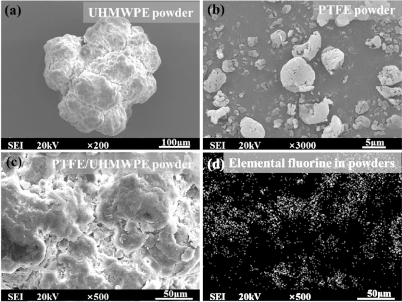
Materials and Fabrication Process. The UHMWPE powder (Figure 1(a)), with a molecular weight of three million, was procured from the Second Beijing Auxiliary Factory. It possesses a melting point of 136 ℃ and a density of 0.92 g/cm3. The PTFE powder (Figure 1(b)) was manufactured by Shenyang Tianyuxiang Micro-powder Material Factory, exhibiting a density of 2.2 g/cm3 and a melting point of 327 ℃. In this study, the blending process for the two powders was conducted using an F-P400H Planetary Ball Mill. Figure 1(c) illustrates the micrographs of the PTFE/UHMWPE blend, wherein the distribution pattern of fluorine elements is depicted in Figure 1(d). The mass ratios selected for the PTFE/UHMWPE blends were as follows: 2/98 and 10/90.
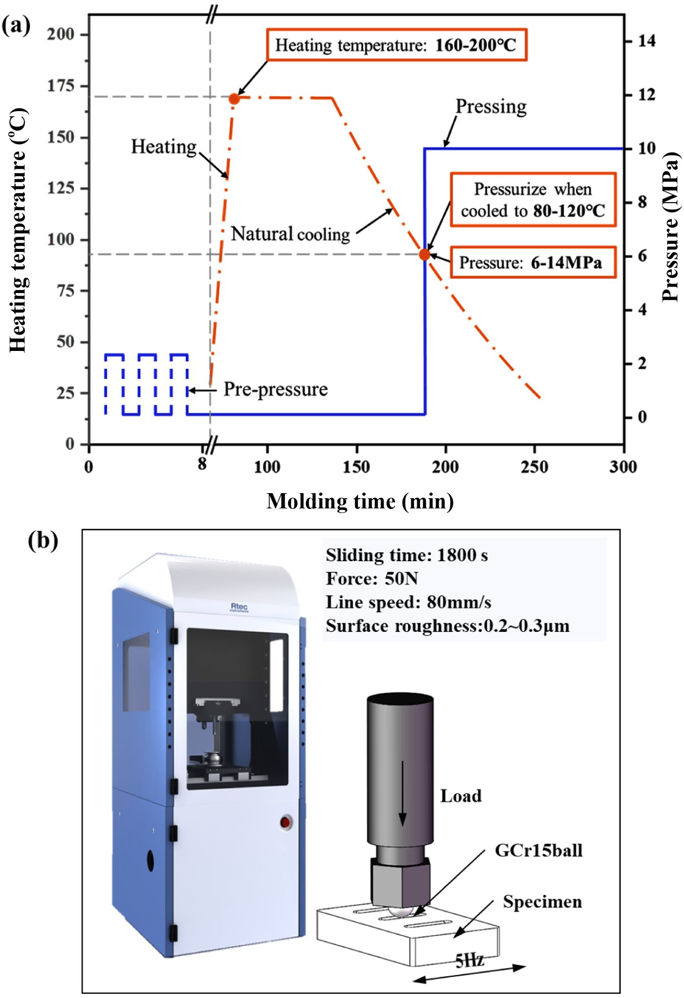
Figure 2(a) illustrates the sample preparation process. The PTFE/UHMWPE blended powder with 2/98 or 10/90 ratio weighing 50 g was dried in an oven and subsequently placed in a rectangular mold. Prior to hot pressing, the blended powder underwent pre-compression to facilitate air escape from the mold. The mold was then heated at the designated temperature for 90 minutes, following which the heating element was turned off, allowing natural cooling of the mold. Once the surface temperature of the die reached the desired pressing temperature, application of selected pressure ensued. After cooling to room temperature, the PTFE/UHMWPE specimen was extracted from the mold for testing purposes. The hot pressing process employed univariate analysis, with respect to the heating temperature (160, 170, 180, 190, 200 ℃), pressing temperature (80, 90, 100, 110, 120 ℃), and pressing pressure (6, 8, 10, 12, 14 MPa). The fixed parameters were a heating temperature of 160 ℃, a pressing temperature of 90 ℃ and a pressing pressure of 10 MPa.
Mechanical and Tribological Tests. A Shore hardness tester (Syntek) was used to characterize the hardness of the sample according to the ISO 868:2003 standard on a shore D scale. The specimens were subjected to indentations at multiple locations, and the average hardness value was subsequently determined. Each measurement employed an indentation load of 22.5 N with a hold time of 15 s. The observed variations in the hardness values remained within a range of 10% around the calculated average.
The details of the friction process and experimental parameters are illustrated in Figure 2(b). The surface roughness of the PTFE/UHMWPE samples was maintained at approximately 300 nm to mitigate the influence of surface roughness on tribological behavior. The friction test was conducted using a multifunctional friction machine (Rtec Instrument Company, USA), where a GCr15 steel ball with a diameter of 6.3 mm was employed for rubbing against the specimens. At least three repeated tests were performed for each specimen, and the wear volume was averaged for three tests.
Characterization. Fourier-transform infrared (FTIR) spectroscopy (Nicolet iS10, Thermo Fisher, Waltham, MA, USA) was used to characterize the characteristic groups of the samples and to study the chemical composition of the blend composites. Thermal analysis studies differential scanning calorimetry (DSC) was employed to analyze thermal behavior of materials used, utilizing a 204 F1 Phoenix DSC calorimeter. The nitrogen gas flow rate was set as 20 mL/min, the heating rate as 10 ℃/min and the heating temperature ranged between 50 ℃ to 200 ℃. Moreover, three-dimensional optical microscopy was performed using MICROLMEA-SUER2, and scanning electron microscopy was used to characterize the geometry of the wear scars.
|
Figure 1 SEM micrographs of (a) UHMWPE powder; (b) PTFE powder; (c) PTFE/UHMWPE powder; (d) The distribution of fluorine in blended powder. |
|
Figure 2 (a) Processing time, pressure, and temperature cycles of PTFE/UHMWPE; (b) Schematics of frictional tests. |
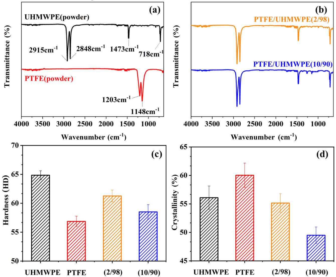
Effect of Content Ratios. The FTIR spectra of the UHMWPE and PTFE samples are presented in Figure 3(a). Figure 3(b) illustrates the FTIR spectra of the PTFE/UHMWPE composites with varying mass ratios. In the pure UHMWPE sample, the characteristic peak at 718 cm-1 can be attributed to the rocking vibration of -C-C- in UHMWPE. The peaks at 1473 and 1462 cm-1 correspond to the bending vibration of CH2. Additionally, the peaks at 2915 and 2848 cm-1 correspond to asymmetric and symmetric stretching vibrations of CH2, respectively, which serve as prominent characteristic features for this UHMWPE.20-23 On the other hand, PTFE's FTIR spectra, being a homopolymer composed of monomeric tetrafluoroethylene units, exhibit highly pronounced split absorption bands around approximately 1203 and 1148 cm-1 that can be attributed to antisymmetric and symmetric stretching vibrations of CF2 groups.24-26 Notably, no new peaks emerged in the infrared spectra of these blends when compared with those obtained from primary ecological powder materials; this observation suggests an absence of chemical reactions during their blending process.
The hardness of UHMWPE, PTFE, and their composites is depicted in Figure 3(c). Due to the lower hardness of PTFE compared to UHMWPE, the surface hardness of the specimen gradually decreases with increasing PTFE content. Although fluctuations in material hardness can arise from variations in the molding process, these fluctuations are within a range of less than 2% and are not the primary focus of analysis in this study. Figure 3(d) illustrates the crystallinity of PTFE/UHMWPE with content ratio of 2/98 and 10/90. The crystallinity decreases as the proportion of PTFE increases. This phenomenon may be attributed to solid PTFE powder hindering the alignment of UHMWPE molecular chains within the melt, with a more pronounced inhibitory effect observed at higher levels of PTFE content.
Effect of Heating Temperature
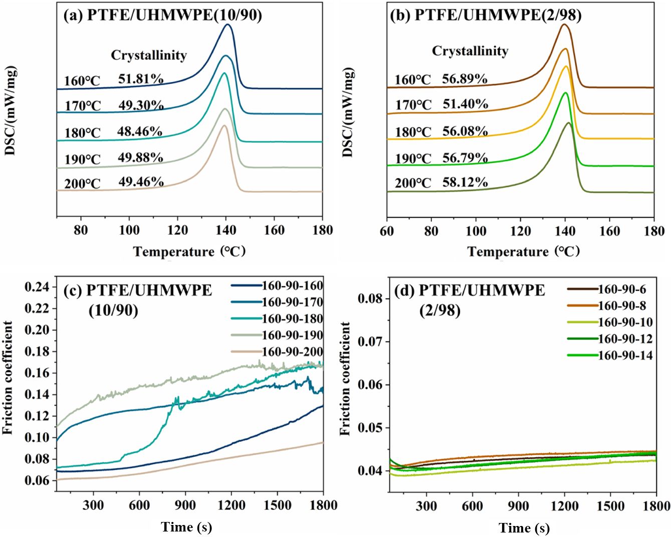
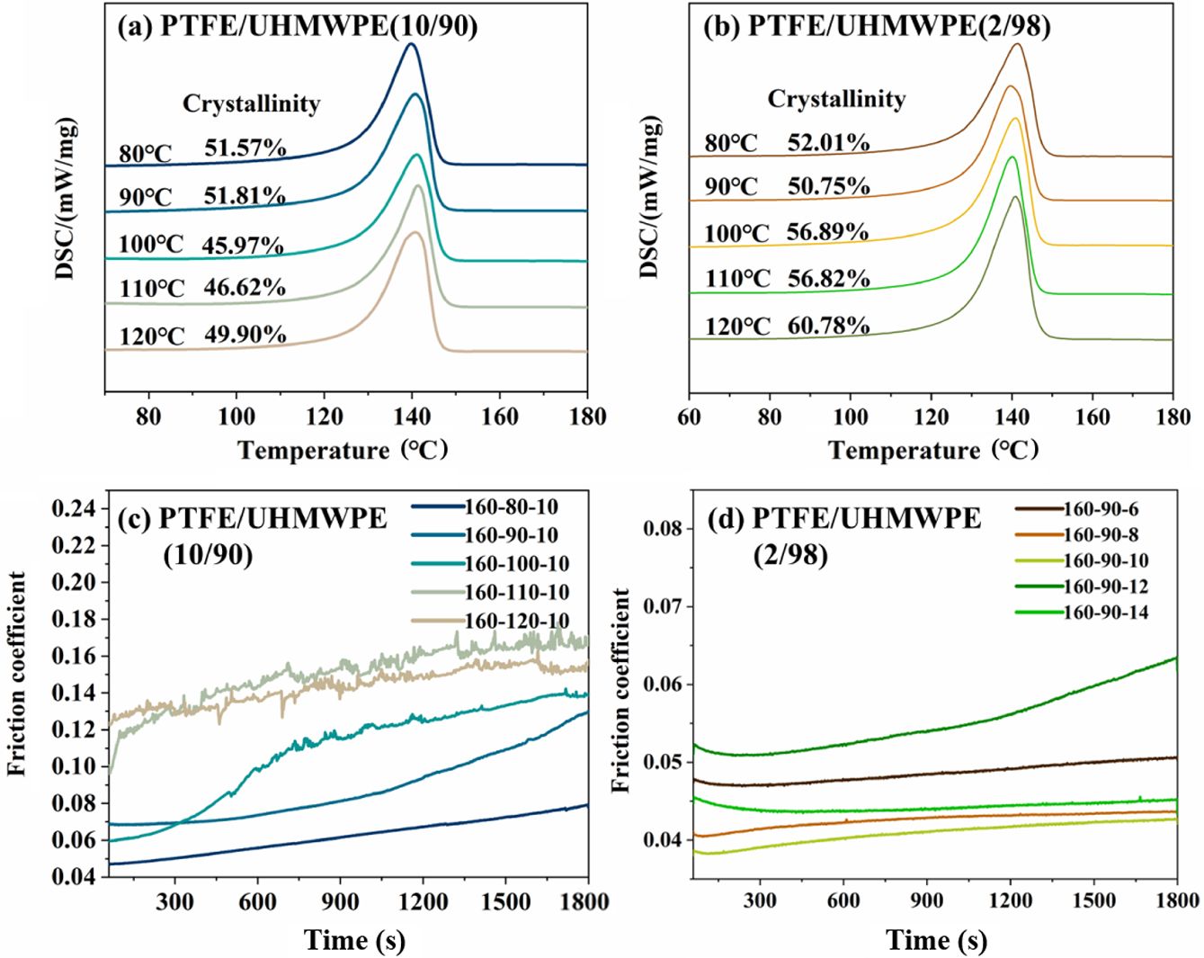
. Figure 4(a) and (b) show DSC curves of PTFE/UHMWPE (10/90 and 2/98). It is observed that the melting range of composites starts at 100 ℃ with a peak melting point of about 140 ℃. The crystallinity is calculated as expressed in Eq.:

where c_UHMWPE is the crystallinity of UHMWPE in PTFE/UHMWPE, ΔH is the enthalpy of fusion of PTFE/UHMWPE, ∆H is the melting enthalpy of 100% crystallized UHMWPE which was taken as 293 J/g,27,28 φ is the weight fraction of UHMWPE in the PTFE/UHMWPE blend composites.
The crystallinity of composites initially decreased and then slightly increased with the increase in heating temperature, as depicted in Figure 4(a) and (b). This phenomenon can be attributed to the enhanced motility activity of UHMWPE polymer chains at a constant PTFE content caused by elevated processing temperature. However, temperatures ranging from 160 ℃ to 180 ℃ did not facilitate sufficient diffusion of the polymer chains, resulting in the disruption of the regular molecular chain arrangement within the UHMWPE primary ecological powder.29 Consequently, this led to the destruction of structured aggregation within the powder and a continuous decrease in composite crystallinity.30 Adequate diffusion of UHMWPE polymer chains occurred when heating temperatures reached 180 ℃ to 200 ℃, followed by rearrangement during cooling that resulted in an increased formation of regular aggregate structures with higher crystallinity.31
The friction coefficient behavior of PTFE/UHMWPE (10/90) samples at different heating temperatures is depicted in Figure 4(c). It exhibits a gradual increase followed by a subsequent decrease with increasing heating temperature. This can be attributed to the fact that at lower temperatures, the PTFE powder within the matrix remains unsoftened, leading to easy dislodgement of the powder during frictional processes of the molded specimen. As the temperature rises, varying degrees of softening occur in the PTFE powder along with diffusion and alignment of UHMWPE molecular chains. Consequently, there is variation in the degree of embedding between PTFE and UHMWPE, wherein higher temperatures result in deeper embedding and greater resistance against peeling off PTFE from the substrate, thereby elevating the friction coefficient. At 200 ℃, excellent fusion between PTFE and UHMWPE occurs without significant spalling during frictional processes; on the contrary, under surface lubrication provided by PTFE, there is a reduction in friction coefficient for these specimens.
The behavior of the in-situ friction coefficient of PTFE/UHMWPE (2/98) specimens at various heating temperatures is depicted in Figure 4(d). Under the same pressing temperature and pressure, the friction coefficient exhibits minimal variation with increasing heating temperature, indicating a stable friction process with reduced fluctuations. This suggests that the spalling of a small amount of PTFE powder not only fails to induce fluctuations in the friction process but also contributes to reducing friction during specimen testing. In contrast to PTFE/UHMWPE (10/90), the composite containing 2% PTFE content shows less sensitivity to changes in heating temperature.
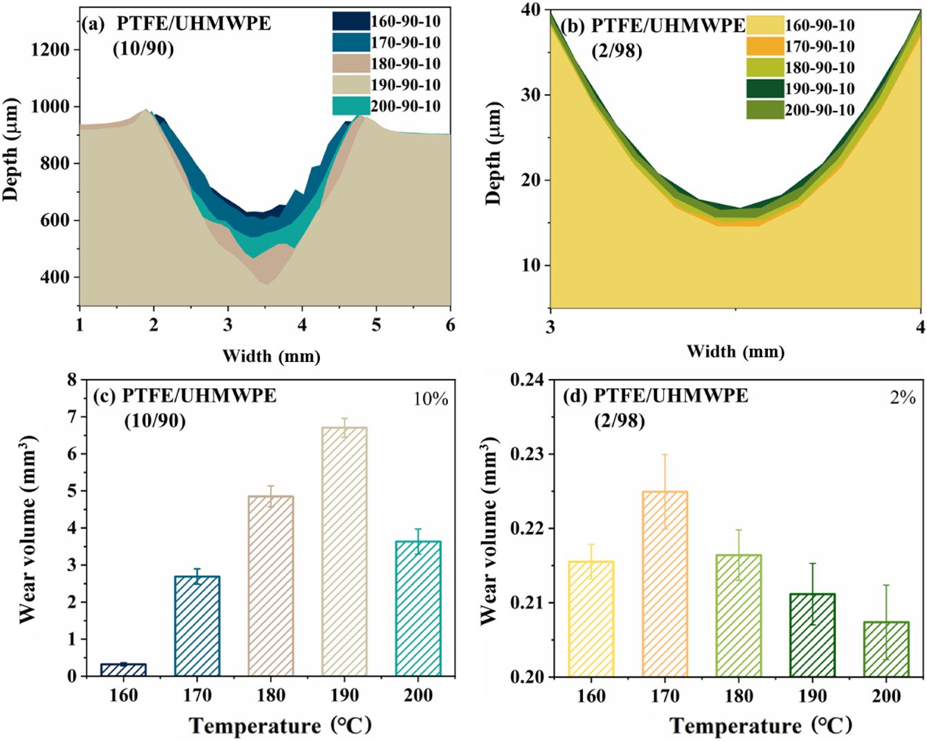
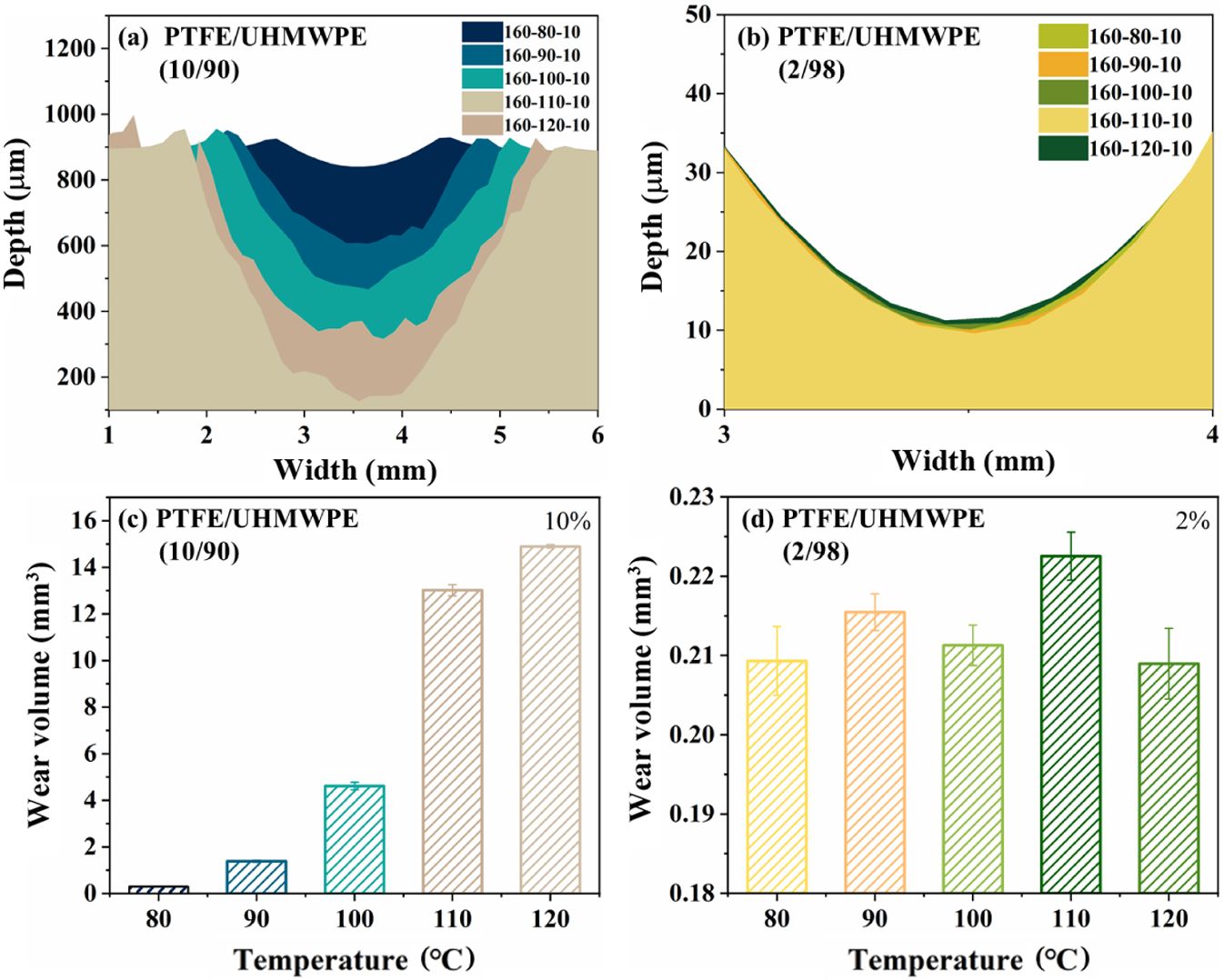
The wear of the specimens is illustrated in Figure 5, where (a) and (b) represent the size of the wear scars for PTFE/UHMWPE (10/90) and PTFE/UHMWP (2/98), respectively. Similarly, (c) and (d) depict the wear amount for PTFE/UHMWPE (10/90) and PTFE/UHMWP (2/98). With increasing heating temperature, there is a clear trend of initially increasing and then decreasing wear amount observed for PTFE/UHMWP (10/90). The minimum wear amount occurs at 160 ℃ while the maximum is observed at 190 ℃. On the other hand, PTFE/UHMWPE (2/98) exhibits smaller variations in wear amount ranging from 0.2078-0.2248 mm3 with a peak value at 170 ℃ and a minimum at 200 ℃, showing only an 8% difference.
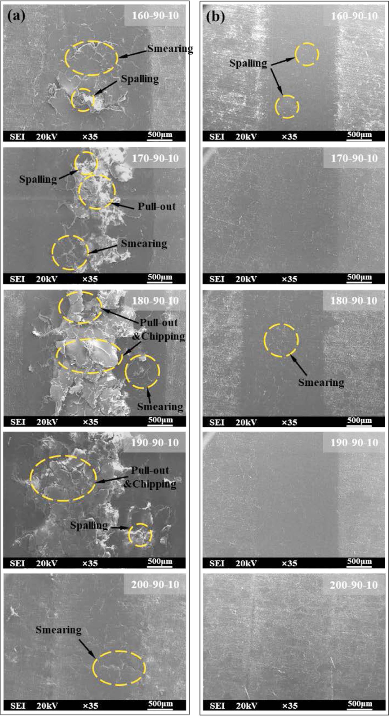
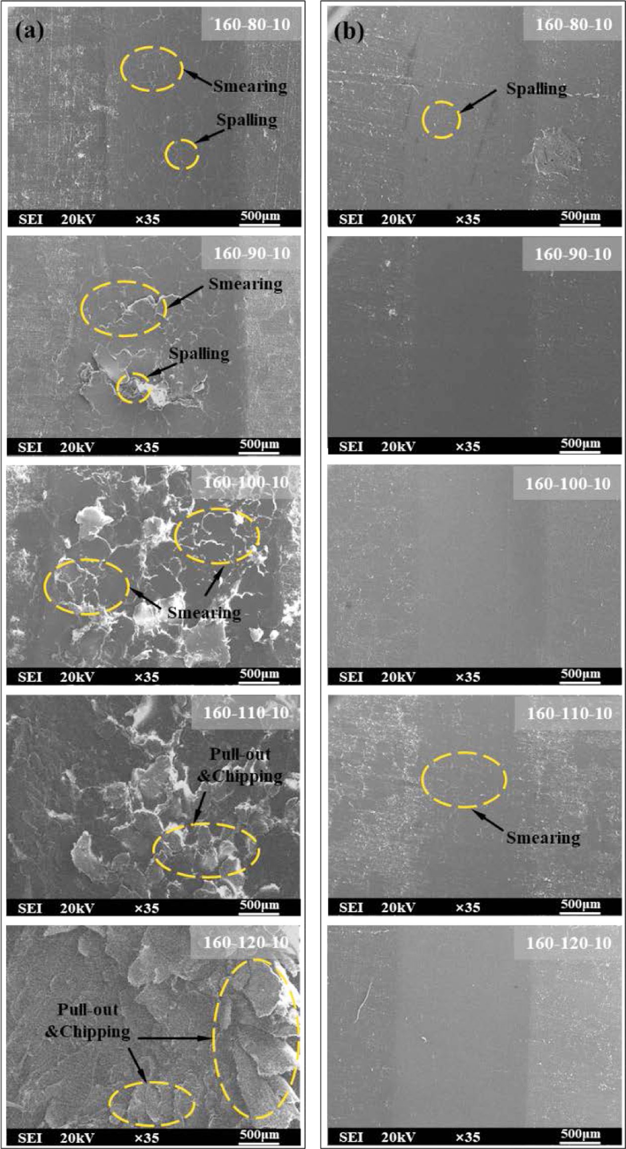
The morphology of their scars (Figure 6) was analyzed using SEM to further investigate the friction and wear mechanisms of the composites. Viscoelastic flow and plastic deformation were observed on all scar surfaces, suggesting that a significant portion of the friction energy is converted into heat during sliding, resulting in elevated temperatures and thermal softening of the friction surface material. As deformation progresses, the shear strength at the adhesion point gradually increases. However, when the shear strength of PTFE/UHMWPE (10/90) surface is lower than that at the adhesion point, detachment or shifting occurs in the softened region. This process leads to exposure of fresh surfaces and subsequent cycles of softening and peeling occur, indicating adhesive wear as one of the major wear mechanisms along with plastic deformation.
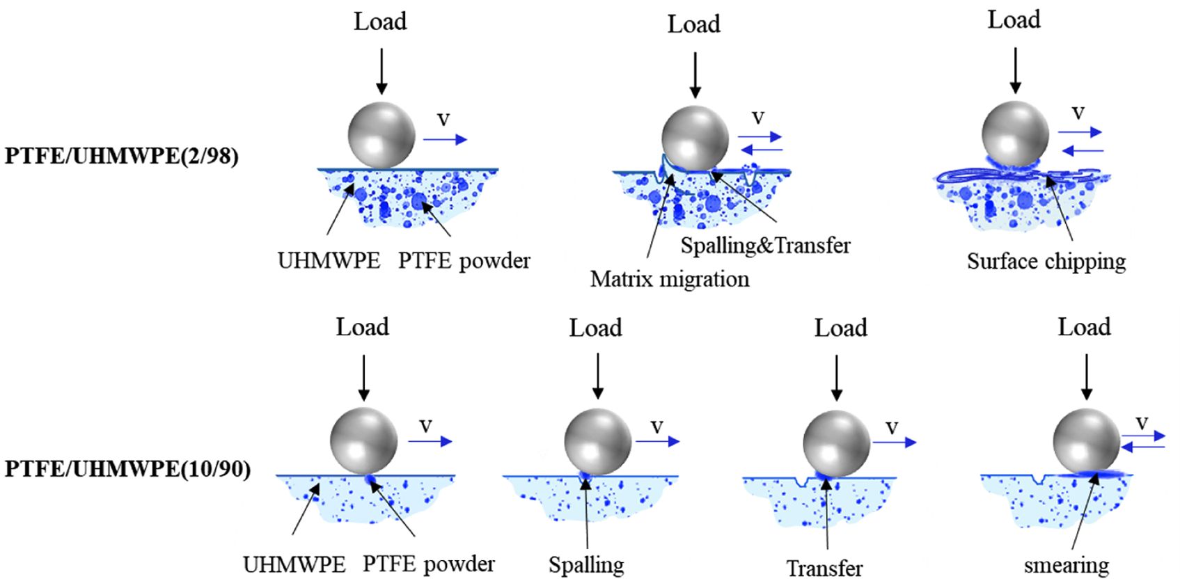
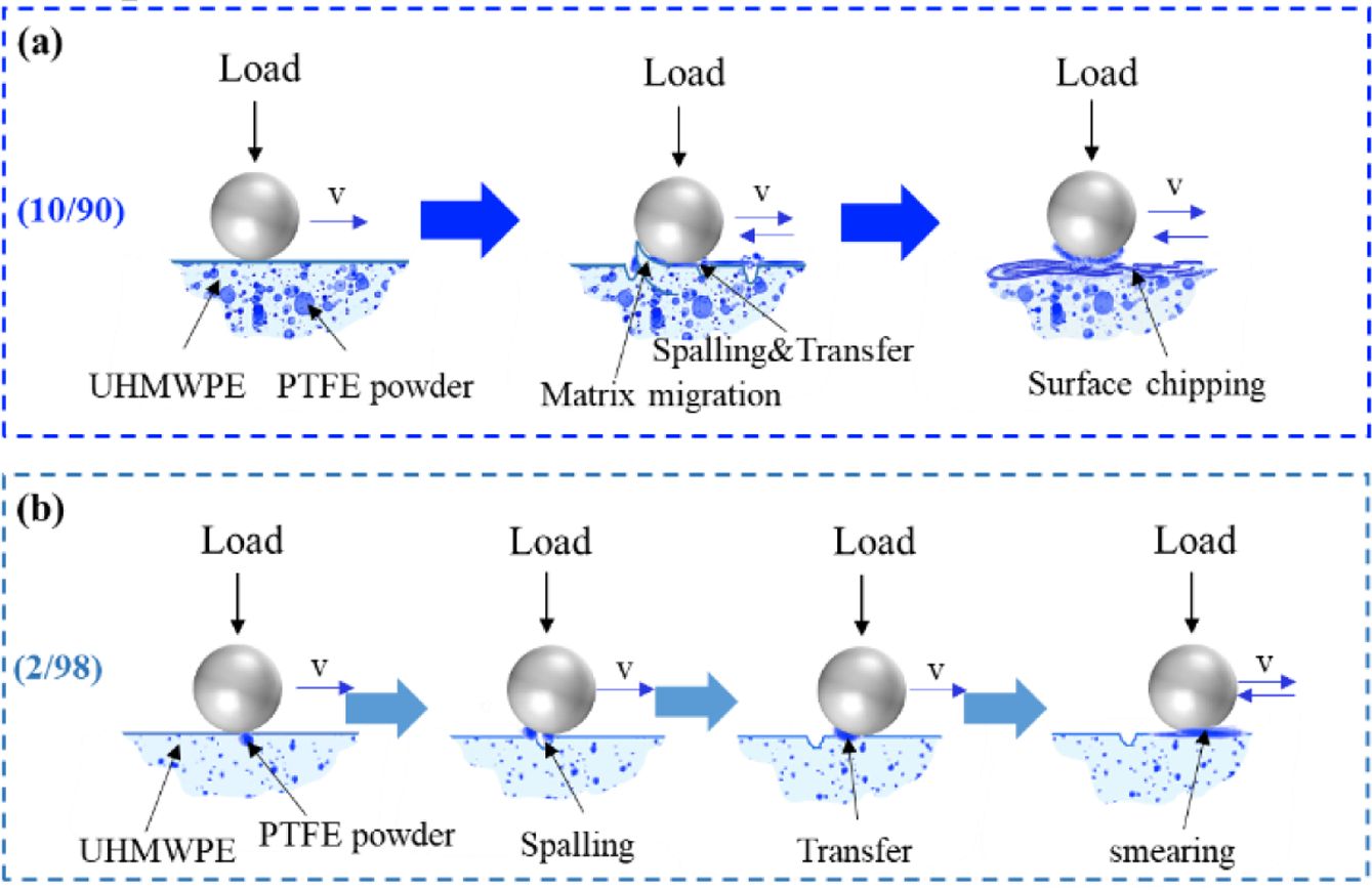
Figure 7(a) illustrates the schematic diagram depicting the wear process of PTFE/UHMWPE (10/90). The plastic flow and adhesive wear of the PTFE/UHMWPE (10/90) wear surface vary with changes in heating temperature. When the heating temperature is below 170 ℃, the PTFE powder within the UHMWPE matrix remains unsoftened. Consequently, during friction, some PTFE powder dislodges from the matrix and adheres to opposing friction surfaces, forming a coating on the worn surface through repeated friction cycles. As the heating temperature increases (180-190 ℃), gradual softening of PTFE powder occurs within the UHMWPE melt due to increased temperatures. Under preset pressurization conditions, different degrees of fusion between PTFE powder and UHMWPE matrix are achieved during holding processes. Adhesive wear manifests in molded specimens during frictional interactions as PTFE drives collective migration of surrounding matrix material. With increasing migration and bonding point area, adhesion strength gradually rises until surpassing shear strength of opposing material, leading to shear damage within PTFE/UHMWPE specimen matrices. At this stage, severe wearing occurs on the surface.32 When heating temperature reaches 200 ℃, solidification performance improves for PTFE/UHMWPE specimens while achieving optimal fusion effects between both materials. During frictional processes at this temperature range, detachment of PTFE does not occur due to excellent lubrication properties resulting in reduced friction coefficient and decreased amount of wear.
The morphology of their scars (Figure 6) was analyzed using SEM to further investigate the friction and wear mechanisms of the composites. Viscoelastic flow and plastic deformation were observed on all scar surfaces, suggesting that a significant portion of the friction energy is converted into heat during sliding, resulting in elevated temperatures and thermal softening of the friction surface material. As deformation progresses, the shear strength at the adhesion point gradually increases. However, when the shear strength of PTFE/UHMWPE (10/90) surface is lower than that at the adhesion point, detachment or shifting occurs in the softened region. This process leads to exposure of fresh surfaces and subsequent cycles of softening and peeling occur, indicating adhesive wear as one of the major wear mechanisms along with plastic deformation.
Figure 7(a) illustrates the schematic diagram depicting the wear process of PTFE/UHMWPE (10/90). The plastic flow and adhesive wear of the PTFE/UHMWPE (10/90) wear surface vary with changes in heating temperature. When the heating temperature is below 170 ℃, the PTFE powder within the UHMWPE matrix remains unsoftened. Consequently, during friction, some PTFE powder dislodges from the matrix and adheres to opposing friction surfaces, forming a coating on the worn surface through repeated friction cycles. As the heating temperature increases (180-190 ℃), gradual softening of PTFE powder occurs within the UHMWPE melt due to increased temperatures. Under preset pressurization conditions, different degrees of fusion between PTFE powder and UHMWPE matrix are achieved during holding processes. Adhesive wear manifests in molded specimens during frictional interactions as PTFE drives collective migration of surrounding matrix material. With increasing migration and bonding point area, adhesion strength gradually rises until surpassing shear strength of opposing material, leading to shear damage within PTFE/UHMWPE specimen matrices. At this stage, severe wearing occurs on the surface.32 When heating temperature reaches 200 ℃, solidification performance improves for PTFE/UHMWPE specimens while achieving optimal fusion effects between both materials. During frictional processes at this temperature range, detachment of PTFE does not occur due to excellent lubrication properties resulting in reduced friction coefficient and decreased amount of wear.
Figure 7(b) illustrates a schematic diagram depicting the wear process of PTFE/UHMWPE (2/98). When the PTFE content is 2%, a minute quantity of PTFE powder is uniformly dispersed within the matrix, resulting in minimal detachment and migration of the powder-driven matrix. Consequently, it exerts negligible impact on the wear surface. The presence of trace amounts of PTFE on the specimen's surface exhibits lubricating properties, thereby reducing both friction coefficient and material wear loss.
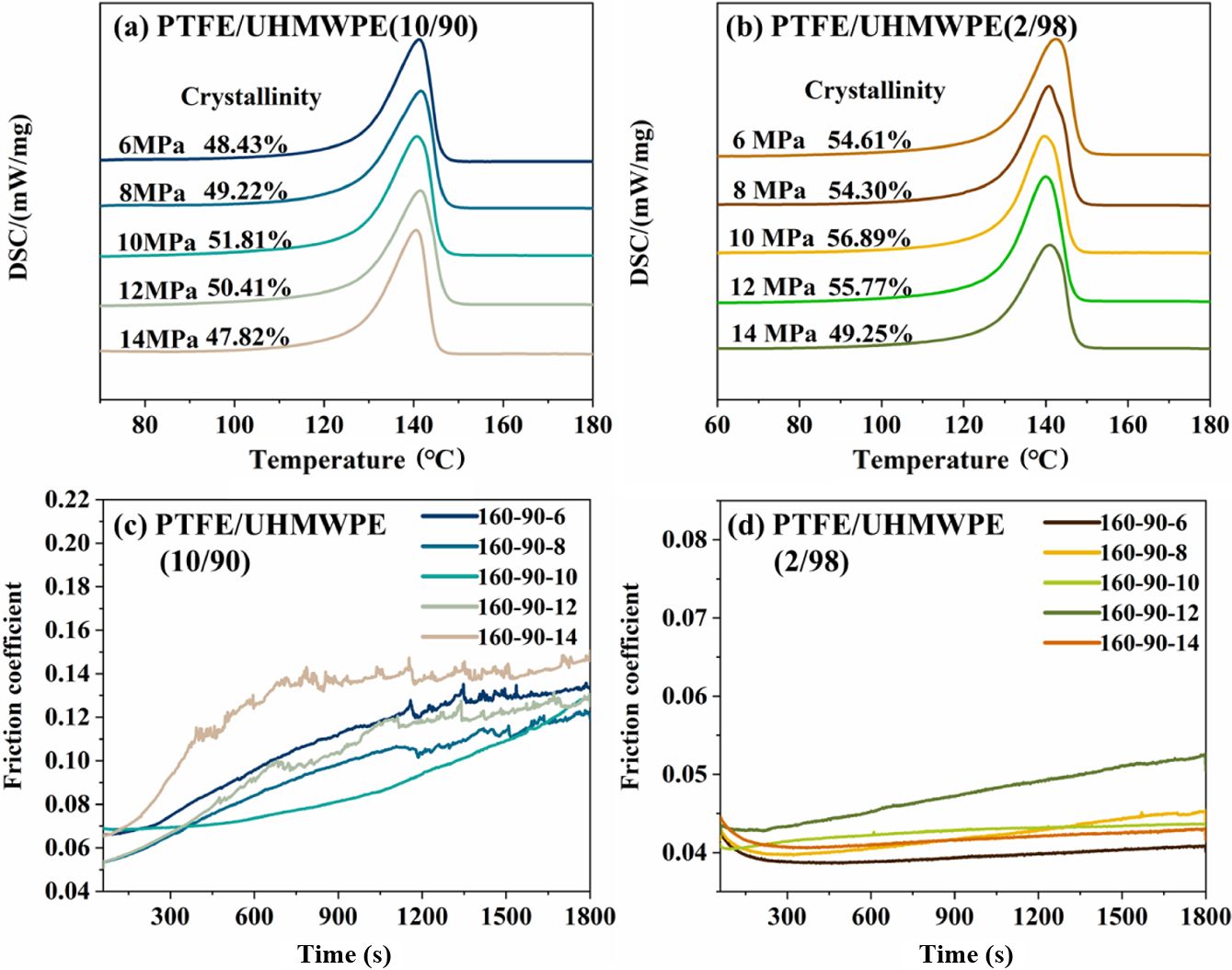
Effect of Pressing Temperatures. The DSC curves for PTFE/UHMWPE (10/90) and PTFE/UHMWP (2/98) composites are presented in Figure 8(a) and (b). It is observed that the melting range of all composites initiates at 100 ℃, with a peak melting point around 140 ℃. Both PTFE/UHMWPE (10/90) and PTFE/UHMWP (2/98) exhibit an initial decrease followed by an increase in crystallinity as the pressing temperature increases. At lower pressing temperatures, the melt exhibits reduced fluidity, resulting in a relatively stationary alignment structure of UHMWPE polymer chains within the matrix. The alignment of molecular chains in the melt is influenced by their alignment in the primary ecological powder, leading to more regular alignment and higher crystallinity. With increasing pressing temperature, enhanced melt fluidity promotes breaking of the primary ecological state and further alignment of polymer chains, causing a subsequent decrease followed by an increase in crystal formation.
As depicted in Figure 8(c), the coefficient of friction for PTFE/UHMWPE (10/90) exhibits a gradual increase with rising pressing temperature, wherein higher temperatures result in greater fluctuations in the coefficient of friction. This phenomenon can be attributed to the increased fluidity of the melt within the mold at elevated pressing temperatures, making it more challenging for PTFE powder to detach from the UHMWPE substrate. At lower pressing temperatures, the friction process facilitates removal of PTFE powder from the matrix and acts as a lubricant, leading to a low coefficient of friction. However, as pressing temperature increases, PTFE powder gradually bonds with the substrate and during subsequent friction processes dislodges from the UHMWPE substrate while driving migration of surrounding substrate material around it, thereby increasing the coefficient of friction. Consequently, due to intermittent shedding of PTFE particles during these processes, significant fluctuations are observed in the coefficient. The behavior of the in-situ friction coefficient of PTFE/UHMWPE (2/98) specimens at various pressing temperatures is illustrated in Figure 8(d). The friction coefficient exhibits minimal variation and remains consistently low. However, an increase in pressing temperature to 110 ℃ leads to a higher friction coefficient for PTFE/UHMWPE (2/98), possibly due to a combination of PTFE powder shedding and substrate migration.
The wear of the specimens at different pressing temperatures is illustrated in Figure 9. An evident increasing trend in the wear amount of UHMWPE/PTFE (10/90) composites is observed with the rise in pressing temperature, as shown in Figure 9(a) and (c). Notably, when the pressing temperature is below 90 ℃, the composite exhibits minimal wear and shallowest wear scars. However, as the pressing temperature increases, both wear loss and depth of abrasion marks gradually increase until reaching a peak at 110 ℃. Subsequently, at 120 ℃, although the material experiences maximum wear amount, there is a decrease in depth while an increase in width of abrasion marks occurs.
When the temperature reaches 110 ℃, the melt in the mold exhibits enhanced fluidity, resulting in increased diffusion and tighter crystal bonding. Consequently, during friction processes, PTFE powder detachment occurs along with substrate material migration, leading to deeper abrasion marks and greater wear. When the application temperature rises to 120 ℃, a substantial amount of base material is extracted during friction processes and coats the bottom and sides of abrasion marks. As a result, these marks become shallower but wider.
At a PTFE content of 2%, the wear of PTFE/UHMWP (2/98) composites significantly decreases while being minimally affected by pressing temperature variations, as shown in Figure 9(b) and (d). Matrix migration caused by shedding PTFE powder is also infrequent; instead, lubrication provided by PTFE powder limits wear in PTFE/UHMWP (2/98) composites to below 0.225 mm3.
The surface morphologies of the samples were characterized using SEM (Figure 10). At lower pressing temperatures, the UHMWPE matrix exhibits a relatively fixed molecular chain arrangement with PTFE wrapped within it. However, the UHMWPE matrix material is not tightly compacted enough, leading to the detachment of PTFE powder from the matrix during friction processes and resulting in localized friction marks. A small portion of detached PTFE powder gets coated onto these abrasion marks through repeated friction, causing slight adhesive wear.33 With increasing pressing temperature, the melt fluidity enhances and crystal arrangements become tighter under pressure. Consequently, stronger bonding forces between PTFE powder and UHMWPE matrix lead to adhesion wear during friction processes. Moreover, higher temperatures result in greater degrees of adhesion wear formation on the surface of abrasion marks in a lamellar structure. However, when PTFE content is low, scattered distribution of PTFE powder within UHMWPE substrates primarily leads to point removal during friction without significant migration across large substrate areas. This results in the formation of a fluoroplastic adhesive layer on counterpart surfaces that reduces material wear.
Effect of Pressing Pressures. The DSC curves for PTFE/UHMWPE composites are presented in Figure 11(a) and (b). For both PTFE/UHMWPE ratios of 10/90 and 2/98, the crystallinity initially increased and then decreased with increasing pressure. This phenomenon can be attributed to the gradual reduction and elimination of sample defects caused by the applied pressure, leading to enhanced diffusion of polymer chains and consequently an increase in crystallinity. However, excessive pressure resulted in a decrease in the crystallinity of PTFE/UHMWPE due to reduced free volume and hindered chain diffusion.
The friction coefficient of PTFE/UHMWPE (10/90) exhibited a non-linear trend with increasing pressure, as depicted in Figure 11(c). Initially, the presence of defects within the matrix and weak bonding between PTFE powder and the matrix led to powder detachment during friction, resulting in increased and fluctuating friction coefficients at low pressures. However, when the pressure was raised to 10 MPa, fewer defects were observed in the melt, leading to improved bonding between PTFE and UHMWPE. Consequently, there was a reduction in powder shedding phenomenon and a decrease in the friction coefficient. At higher pressures (14 MPa), enhanced melt fluidity promoted the formation of oriented molecular chain structures under applied tensile force. This resulted in matrix migration during friction and an increase in the friction coefficient. The friction coefficient of PTFE/UHMWPE (2/98) in Figure 11(d) is comparable to that observed in section 2.3 for the same material composition. A lower content of PTFE powder results in a stable friction process with a reduced coefficient of friction. The addition of a small amount of PTFE powder mitigates the adverse impact of pressure on the friction properties exhibited by the specimens.
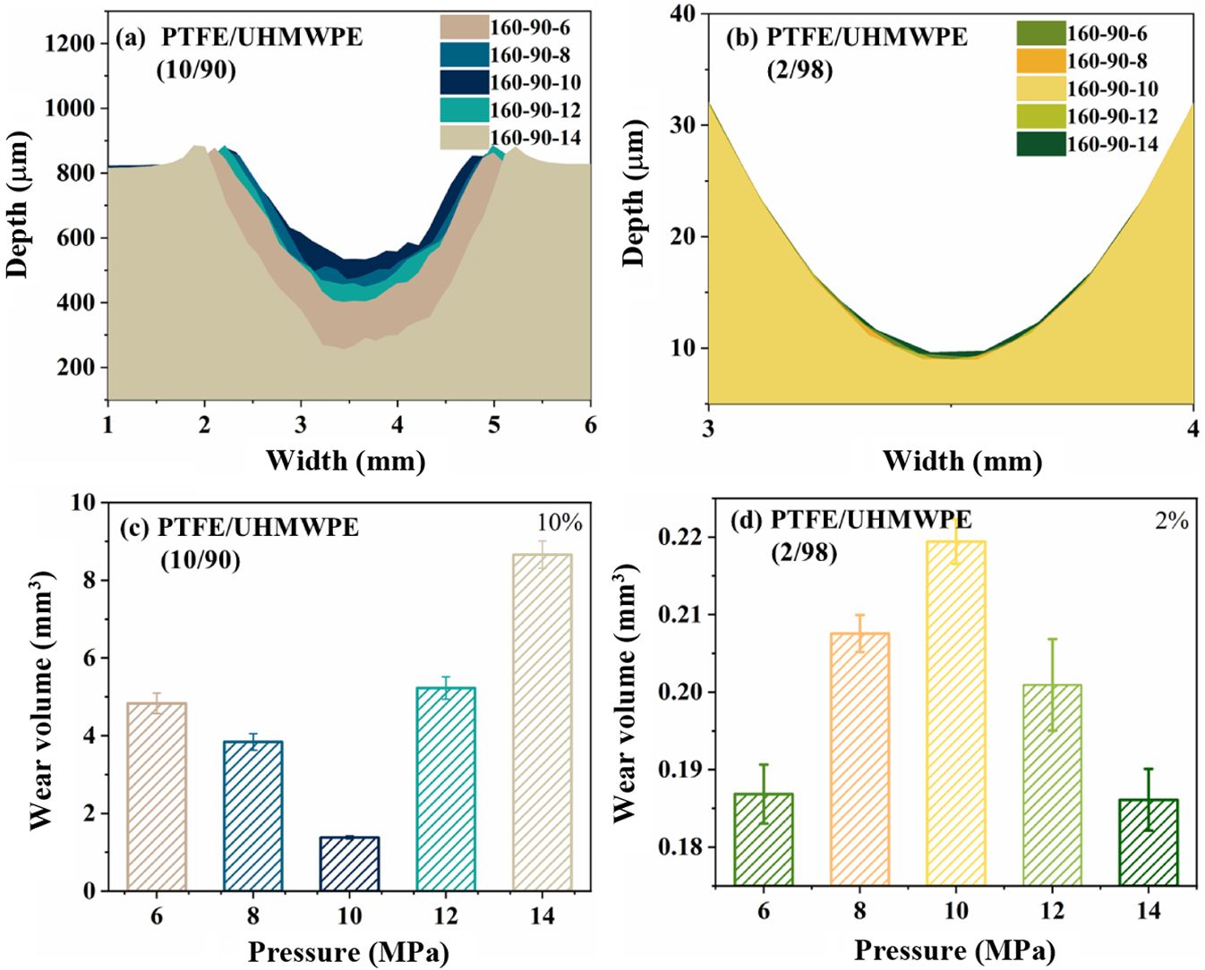
The wear of the specimens at different pressing pressures is illustrated in Figure 12. The wear behavior of PTFE/UHMWPE (10/90) composite initially decreases and then increases with increasing pressure, as shown in Figure 12(a) and (c). This can be attributed to imperfect bonding between the PTFE powder and UHMWPE matrix, caused by melt defects such as holes resulting from lower pressures, which enhance material wear. At a pressure of 10 MPa, the melt defects are almost eliminated, leading to a higher degree of integration between the two materials. Consequently, the PTFE powder exhibits improved adhesion during frictional processes, with minimal point removal that acts as a lubricant and reduces specimen wear. However, excessive pressure causes polymer structure orientation and weakens the bonding force between PTFE powder and matrix, resulting in significant removal of PTFE powder under external forces and increased wear rate. In contrast, for composites containing 2% PTFE content (PTFE/UHMWP (2/98)), as shown in Figure 12(b) and (d), the amount of wear is significantly reduced regardless of applied pressure due to effective lubrication provided by the presence of PTFE powder.
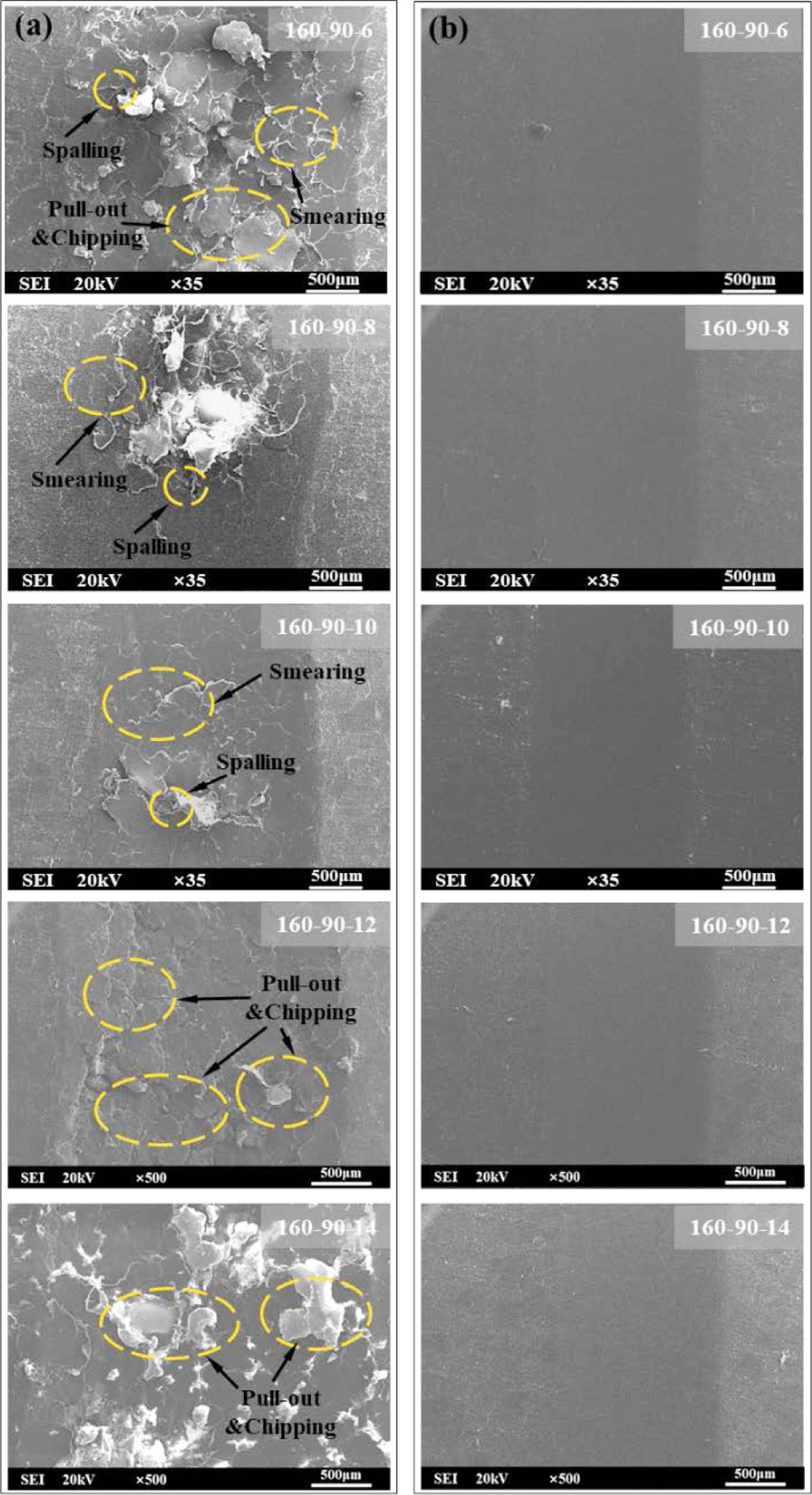
The SEM images of the wear scars are presented in Figure 13. When the pressing pressure is low, the blend exhibits a lower degree of solidification. During the friction process, PTFE adheres to the surface of the opposing friction part and relocates on the substrate under tensile force, resulting in surface chipping. The adhesive wear gradually decreases with increasing applied pressure. At pressures ranging from 12-14 MPa, elevated pressure causes significant flow of melt in the mold. This leads to exclusive collimation of numerous polymer chains along the direction of melt flow and detachment of some polymer chains from amorphous regions, causing structural defects in specimens and exacerbating PTFE/UHMWPE wear. Furthermore, bonding force between PTFE powder and oriented UHMWPE is reduced, leading to flaking of PTFE powder under external forces and migration of matrix material, thereby intensifying wear effects. This phenomenon becomes more pronounced at a PTFE content level of 10%. However, when the PTFE content is only 2%, a small amount of PTFE powder peels off to act as a lubricant on the friction surface, significantly reducing material wear.
|
Figure 3 FTIR spectra: (a, b), hardness; (c) crystallinity; (d) of pure UHMWPE, PTFE and their composites |
|
Figure 4 The crystallinity: (a, b) and friction coefficient; (c, d) of PTFE/UHMWPE composites (10/90, 2/98) at various heating temperatures. |
|
Figure 5 The wear scars: (a, b) and wear loss; (c, d) of PTFE/ UHMWPE composites (10/90, 2/98) at various heating temperatures. |
|
Figure 6 Wear morphologies of (a) PTFE/UHMWPE (10/90); (b) PTFE/UHMWPE (2/98) at various heating temperatures. |
|
Figure 7 Schematic diagram of wear process of (a) PTFE/UHMWPE (10/90); (b) PTFE/UHMWPE (2/98). |
|
Figure 8 The crystallinity: (a, b) and friction coefficient; (c, d) of PTFE/UHMWPE composites (10/90, 2/98) at various pressing temperatures. |
|
Figure 9 The wear scars: (a, b) and wear loss; (c, d) of PTFE/ UHMWPE composites (10/90, 2/98) at various heating temperatures. |
|
Figure 10 Wear morphologies of (a) PTFE/UHMWPE (10/90); (b) PTFE/UHMWPE (2/98) at various pressing temperatures. |
|
Figure 11 The crystallinity: (a, b) and friction coefficient; (c, d) of PTFE/UHMWPE composites (10/90, 2/98) at various pressing pressures. |
|
Figure 12 The wear scars: (a, b) wear loss; (c, d) of PTFE/UHMWPE composites (10/90, 2/98) at various pressing pressures. |
|
Figure 13 Wear morphologies of (a) PTFE/UHMWPE (10/90); (b) PTFE/UHMWPE (2/98) at various pressing pressures. |
The PTFE/UHMWPE composites were prepared by adjusting the molding parameters and varying the content of PTFE. The findings revealed that the frictional behavior and wear mechanisms of the composites are influenced by both the PTFE content and molding process employed. The key conclusions can be summarized as follows:
(1) With an increase in PTFE content, there is a decrease in hardness and crystallinity observed in the PTFE/UHMWPE composites. This reduction in hardness can be attributed to the inherently low hardness of PTFE powder itself when added to the composites.
(2) Incorporating PTFE powder hampers to some extent both untwisting and diffusion processes occurring within UHMWPE polymer chains, leading to a decrease in blend crystallinity as more PTFE powder is added.
(3) Altering the molding process significantly impacts wear mechanisms exhibited by PTFE/UHMWPE (10/90) composites; adhesive wear (including slight abrasion, smearing, tearing off), extrusion deformation, and plastic flow were identified as primary modes of wear for this composition ratio blend.
(4) The optimal processing parameters for achieving reduced frictional behavior and improved wear resistance are heating temperature at 160 ℃ combined with pressing temperature at 80 ℃ under a pressure level set at 10 MPa.
- 1. Chhetri, S.; Bougherara, H. A. Comprehensive Review on Surface Modification of UHMWPE Fiber and Interfacial Properties. Compos. Part A: Appl. Sci. Manuf. 2021, 140, 106146.
-

- 2. Alam, F.; Choosri, M.; Gupta, Tejendra K.; Varadarajan, K. M.; Choi, D.; Kumar, S. Electrical, Mechanical and Thermal Properties of Graphene Nanoplatelets Reinforced UHMWPE Nanocomposites. Mater. Sci. Eng. B 2019, 241, 82-91.
-
- 3. Raffi, N. M.; Srinivasan, V. A Study on Wear Behavior of γ-UHMWPE Sliding Against 316L Stainless Steel Counter Face. Wear 2013, 306, 22-26.
-
- 4. Chen, J.; Zhu, J.; Li, Q.; Wu, Ho.; Guo, S. Y.; Qiu, J. H. Constructing 3D Interconnected CNTs Network in PA6 Composites with Well-dispersed UHMWPE for Excellent Tribological and Heat Dissipation Properties. Compos. Part B: Eng. 2022, 246, 110252.
-
- 5. Gu, J. W; Li, N.; Tian, L. D; Lv Z. Y.; Zhang, Q. Y. High Thermal Conductivity Graphite Nanoplatelet/UHMWPE Nanocomposites. Rsc. Adv. 2015, 5, 36334-36339.
-
- 6. Steven, M. K. UHMWPE Biomaterials Handbook: Ultra High Molecular Weight Polyethylene in Total Joint Replacement and Medical Devices; Academic Press: London, 2009.
- 7. Chen, S.; Li, J.; Jin, Y. L; Xiao, J.; Khosla, T.; Hua, M.; Jia, D.; Duan, H. T. Fabrication of Polyimide-modified UHMWPE Composites and Enhancement Effect on Tribological Properties. Polym. Plastics Technol. Eng. 2018, 57, 700-707.
-
- 8. Chang, B. P.; Akil, H. M.; Nasir, R. B. M. Comparative Study of Micro-and Nano-ZnO Reinforced UHMWPE Composites Under Dry Sliding Wear. Wear, 2013, 297, 1120-1127.
-
- 9. Chukov, D. I.; Stepashkin, A. A.; Maksimkin, A. V.; Tcherdyntsev, V. V.; Kaloshkin, S. D.; Kuskov, K. V.; Bugakov V. I. Investigation of Structure, Mechanical and Tribological Properties of Short Carbon Fiber Reinforced Uhmwpe-matrix Composites. Compos. Part B: Eng. 2015, 76, 79-88.
-
- 10. Chen, S.; Li, J.; Wei. L.; Jin, Y. L.; Shang, H. F.; Meng, H.; Duan, H. T. Tribological Properties of Polyimide-modified UHMWPE for Bushing Materials of Seawater Lubricated Sliding Bearings. Tribology International, 2017, 115, 470-476.
-
- 11. Biswas, S. K.; Vijayan, K. Friction and Wear of PTFE-a Review. Wear, 1992, 158, 193-211.
-
- 12. Khedkar, J.; Negulescu, I.; Meletis, E. I. Sliding Wear Behavior of PTFE Composites. Wear, 2002, 252, 361-369.
-
- 13. Chen, W. X.; Li, F.; Han, G.; Xia, J. B.; Wang, L.Y.; Tu, J. P.; Xu Z. D. Tribological Behavior of Carbon-nanotube-filled PTFE Composites. Tribology Letters, 2003, 15, 275-278.
-
- 14. Dhanumalayan, E.; Joshi, G. M. Performance Properties and Applications of Polytetrafluoroethylene (PTFE)-a Review. Advanced Compos. Hybrid Mater. 2018, 1, 247-268.
-
- 15. Lin, Y.; Guo, Z.; Yuan, C. Effects of Solid Lubricants on the Tribological Behavior of Steel-backed UHMWPE Fabric Composites. J. Appl. Polym. Sci. 2022, 139, 51674.
-
- 16. Gürgen, S.; Çelik, O. N.; Kuşhan, M. C. Tribological Behavior of UHMWPE Matrix Composites Reinforced with PTFE Particles and Aramid Fibers. Compos. Part B: Eng. 2019, 173, 106949.
-
- 17. Wu, J. J.; Buckley, C. P.; O’Connor, J. J. Mechanical Integrity of Compression-moulded Ultra-high Molecular Weight Polyethylene: Effects of Varying Process Conditions. Biomaterials, 2002, 23, 3773-3783.
-
- 18. Gul, R. M.; McGarry, F. J. Processing of Ultra‐high Molecular Weight Polyethylene by Hot Isostatic Pressing, and the Effect of Processing Parameters on Its Microstructure. Polym. Eng. Sci. 2004, 44, 1848-1857.
-
- 19. Zhou, X. C.; Yang, C. Z.; Huang, J.; Liu, X. S.; Zhong, D.; Wang, P.; Wan, Gao. Tribological Behavior of UHMWPE in Water Lubrication: the Effect of Molding Temperature. Industrial Lubrication and Tribology, 2022, 74, 211-218.
-
- 20. Cai, T.; Zhan, S. P.; Yang, T.; Li, Yin. H.; Jia, D.; Tu, J. S.; Li, J.; Duan, H. T. Study on the Tribological Properties of UHMWPE Modified by UV-induced Grafting Under Seawater Lubrication. Tribology International, 2022, 168, 107419.
-
- 21. Cheng, B. X.; Duan, H. T.; Chen, S.; Shang, H. F.; Li, Jian.; Shao, T. M. Phase Morphology and Tribological Properties of PI/UHMWPE Blend Composites. Polymer, 2020, 202, 122658.
-
- 22. Chih, A.; Ansón-Casaos, A.; Puértolas, J. A. Frictional and Mechanical Behaviour of Graphene/UHMWPE Composite Coatings. Tribology International, 2017, 116, 295-302.
-
- 23. Bracco, P.; Brunella, V.; Luda, M. P.; Zanetti, M.; Costa, L. Radiation-induced Crosslinking of UHMWPE in the Presence of co-agents: Chemical and Mechanical Characterisation. Polymer, 2005, 46, 10648-10657.
-
- 24. Wang, R.; Xu, G.; He, Y. Structure and Properties of Polytetrafluoroethylene (PTFE) Fibers. e-Polymers, 2017, 17, 215-220.
-
- 25. Xu, J. L.; Gowen, A. A. Time Series Fourier Transform Infrared Spectroscopy for Characterization of Water Vapor Sorption in Hydrophilic and Hydrophobic Polymeric Films. Spectrochimica Acta Part A: Molecular and Biomolecular Spectroscopy, 2021, 250, 119371.
-
- 26. Henri, V.; Dantras, E.; Lacabanne, C, Dieudonne, A.; Koliatene, F. Thermal Ageing of PTFE in the Melted State: Influence of Interdiffusion on the Physicochemical Structure. Polymer Degradation and Stability, 2020, 171, 109053.
-
- 27. Belotti, L. P.; Vadivel, H. S.; Emami, N. Tribological Performance of Hygrothermally Aged UHMWPE Hybrid Composites. Tribology International, 2019, 138, 150-156.
-
- 28. Rudnik, E.; Dobkowski, Z. Thermal Degradation of UHMWPE. J. Thermal Analysis, 1997, 49, 471-475.
-
- 29. Guenoun, G.; Faou, J. Y.; Régnier, G.; Schmitt, N.; Roux, S. PTFE Crystallization Mechanisms: Insight From Calorimetric and Dilatometric Experiments. Polymer, 2020, 193, 122333.
-
- 30. Hu, Y. L.; Zhao, W. J.; Li, Z. Research on the Microstructure of UHMWPE Primary Particles and Mechanical Performances of Products Under Different Processing Conditions. Mater. Sci. Technol. 2020, 28, 1-10.
- 31. Chen S, Li J, Wei L, Jin, Y. L.; Cheng, B. X.; Chen, W.; Duan H. T. Comparative Effects of Rocket-grade Hydrogen Peroxide Solution on POM and UHMWPE: Aging Behaviors and Tribological Properties. Colloid and Polym. Sci. 2018, 296, 1087-1096.
-
- 32. Unal, H.; Sen, U.; Mimaroglu, A. An Approach to Friction and Wear Properties of Polytetrafluoroethylene Composite. Mater. Design, 2006, 27, 694-699.
-
- 33. Briscoe, B. J.; Sinha, S. K. Wear of Polymers. Proceedings of the Institution of Mechanical Engineers, Part J: Journal of Engineering Tribology, 2002, 216, 401-413.
-
- Polymer(Korea) 폴리머
- Frequency : Bimonthly(odd)
ISSN 2234-8077(Online)
Abbr. Polym. Korea - 2025 Impact Factor : 1.0
- Indexed in SCIE
 This Article
-
2026; 50(2): 187-197
Published online Mar 25, 2026
- 10.7317/pk.2026.50.2.187
- Received on Dec 4, 2024
- Revised on Apr 9, 2025
- Accepted on Apr 9, 2025
Services
- Full Text PDF
- Abstract
- ToC
- Acknowledgements
- Conflict of Interest
Introduction
Experimental
Results and Discussion
Conclusions
- References
Shared
Correspondence to
- Jia Dan
-
*State Key Laboratory of Special Surface Protection Materials and Application Technology,
China Academy of Machinery Wuhan Research Institute of Materials Protection Co., Ltd.
**Hubei Longzhong Laboratory - E-mail: jiadan0510@163.com
- ORCID:
0000-0002-3589-293X
Hyecheon Building(Room 601), #354, Gangnam-Daero, Gangnam-Gu, Seoul 06242, Korea
TEL : 82-2-568-3860, 561-5203, 569-3860 FAX : 82-2553-6938 E-mail: polymer@polymer.or.kr